Airmar Power Tee and Field Attachable Connector—NMEA 2000® User Manual
Field-attachable devicenet connector, Wiring diagram, Nmea 2000
Wiring Diagram
Field-Attachable DeviceNet Connector
NMEA 2000
®
Compatible
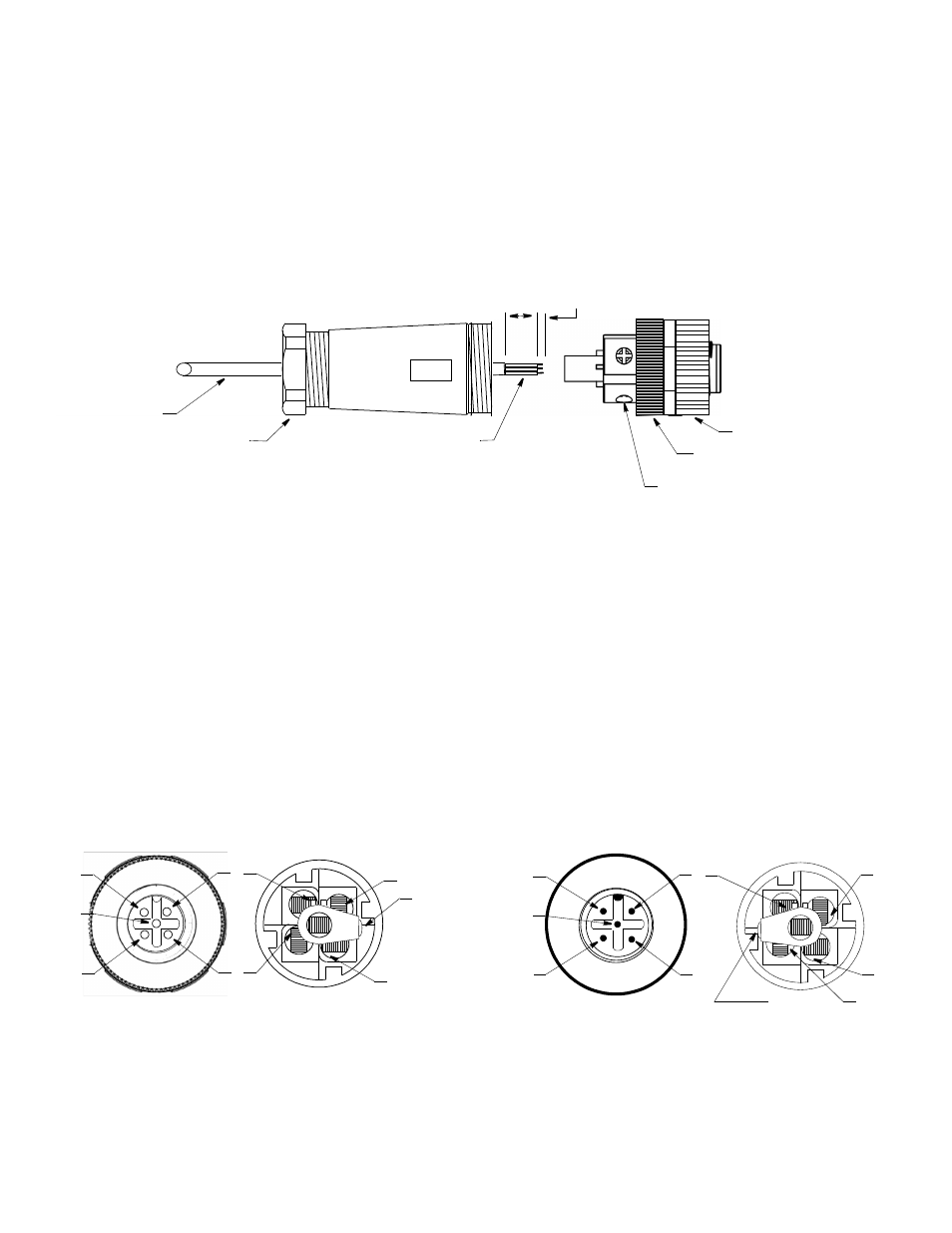
Assembling and Wiring the Connector
NOTE: The instructions are the same for both male and female connectors.
1. Remove a connector from the bag and unscrew the terminal assembly from the body of the connector (see Figure 1).
2. Push the cable through the compression nut and the body of the connector including the cable gland inside until the cable projects
through the opposite end. Do not tighten the compression nut at this time.
3. Strip 25mm (1”) of the outer jacket and foil shield from the cut end of the cable to expose the colored conductors.
4. Strip 5mm (3/16") of insulation from the end of each colored conductor.
5. Cover the bare wire with electrical tape or shrink tubing (not supplied).
6. Secure each conductor to the appropriate terminal by tightening the set screw. Follow the color code below (see Figure 2).
7. Repeat until all the conductors are secured.
8. Attach the terminal assembly to the body by rotating the plastic ring in a clockwise direction (see Figure 1).
9. Secure the compression nut to the body by rotating it in a clockwise direction. This will hold the cable firmly in place.
10.Repeat the steps for each connector.
NMEA 2000® is a registered trademark of the National Marine Electronics Association.
Figure 1. Assembling connector (Turck female connector shown)
set screw (5)
19mm
(3/4")
5mm
(3/16")
metal coupling nut
(connects terminal assembly to body)
Copyright © 2012 Airmar Technology Corp.
cable
compression
conductor (5)
plastic ring
nut
body
terminal assembly
V+
V-
SHD
CANL
exterior view
interior view
male connector
interior view
exterior view
female connector
Figure 2. Connecting to the terminals (Turck connectors shown)
5
NOTE:
set screw
Copyright © 2012 Airmar Technology Corp.
faces right
2
1
3
4
5
1
2
4
3
5
5
blue terminal
set screw
faces left
1
4
Wiring Key
1. Silver
SHD (bare)
2. Red
V+
3. Black
V-
4. White
CAN
H
5. Blue
(CAN
L
)
blue terminal
V+
V-
SHD
CANH
CANL
2
3
NOTE:
4
CANH
17
-4
70
-0
1 re
v.
05
05
/21
/12