Parts list a / assembly diagram a – All Power APC4017 User Manual
Page 9
Advertising
PAGE 9
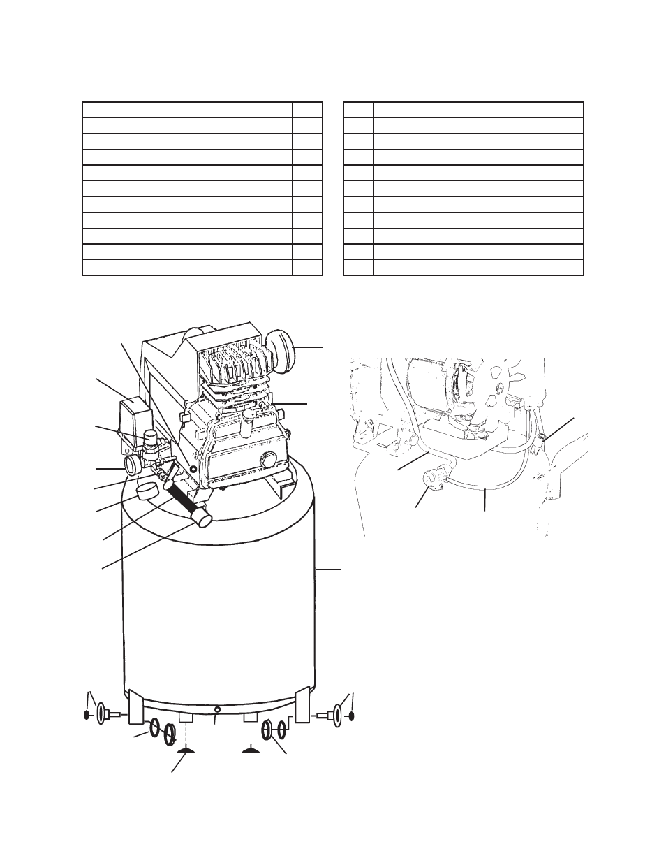
PARTS LIST A / ASSEMBLY DIAGRAM A
Part
Description
Qty.
1A ON/OFF Power Switch
1
2A Tool Pressure Adjuster
1
3A Tank Pressure Gauge
1
4A Tool Pressure Gauge
1
5A Pressure Release Valve
1
6A Air Flow Valve
1
7A Air Filter
1
8A Air Flow Lid
1
9A Air Tank
1
10A Water Drain Valve
1
Part
Description
Qty.
11A Quick Release Coupler
1
12A Rubber Wheel with Bolt
2
13A Washer
2
14A Nut
2
15A Fitting
1
16A Oil Drain Plug with Gasket
1
17A Foot
2
18A Unloader Valve
1
19A Polyurethane Unloader Tube
1
20A Copper Air Tube
1
1A
2A
4A
5A
7A
8A
9A
10A
12A
13A
14A
15A
11A
16A
17A
18A
19A
20A
(Rear View with motor cover removed.)
3A
6A
12A
Advertising