Standard work, Process description – Allmand Brothers NIGHT LITE PRO II V User Manual
Page 8
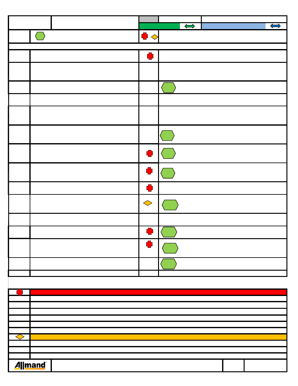
STANDARD WORK
1
2
3
4
5
6
7
8
9
10
11
13
14
15
1
7
7,8,9
12,13
10
Take the two eye terminals and install on to the grounding
stud. Install hex nut to grounding stud.
12
in bottom side of control box.
Looking from left to right (inside control box) are 1 2 3 4
transformer wires. Black goes to #1, Red w/ Black Stripe
Check that cord has enough slack for full rotation of the tower and enough slack to reach all electrical connections.
PROCESS DESCRIPTION
SW #
AS1002
Insert tower wire cord into cord grip (310033) on roof
panel.
Open door to access the control box. Pull wire into unit.
(32" required from bottom of cord grip to longest wire.)
Take tower wire and insert through cord grip
Doors may be removed at hinge points to allow inside
access to the tower during installation.
Drop chain hooks through center of nycoil and hook to
Remove hydraulic pump mount cover. Keep Hardware.
and 1/4-20 hex nut (044021). Replace Cover.
Attach tower tab to pump mount w/ 1/4-20 hex bolt (046010)
Failure to follow electrical code when attaching terminals may result in property damage, serious injury, or death.
QUALITY INSPECTIONS
goes to #2, Red goes to #3, Blue goes to #4.
Split each green wire with each of the colored wires
Failure to apply the proper torque may result in property damage, serious injury, or death.
Failure to prevent engine start-up while working inside of unit may result in property damage, serious injury, or death.
See "Section 4" for additional steps.
This information is continued on additional page(s).
SAFETY PRECAUTIONS
Moving or lowering the tower with a person in the path of or beneath the tower may result in serious injury or death.
Attach loose cord (outside of unit) to lift bar
close lever to secure.
STANDARD OPTION:
NON STANDARD OPTION:
NO.
PRODUCT/PROCESS
DESCRIPTION
PROCESS
/
COMMENT
Finish Assembly of NLPro II Vertical
Tower
WORKSTATION:
Any
Use caution when lifting and positioning the tower to prevent
eye bolts. Lift tower and position vertically on the unit.
tower from falling or swinging and injuring people.
Use overhead crane with safe working load
3/8" eye bolts required to be attached to both sides of the lowest
Remove 3/8-16 bolts from top front of unit.
Keep hardware for light tower installation.
hardware for reattachment after tower installation.
of minimum 500 lbs to lift the tower.
tower section. (Through provided holes on each bracket.)
Use chain with two hooks with safe working load
of 500 lbs minimum.
LIGHT TOWER ASSEMBLY:
with #10 cush clamp (310212)
Insure that battery cables are removed from the
battery and remove the keys from the engine.
DO NOT proceed until precautions have been taken to
prevent engine from starting.
allow it to be moved.
Remove any bolts, straps and packaging from tower to
Remove lift bar (102846P) from unit and set aside. Keep
Attach Tower to Unit with hardware removed in Step 4.
Be sure to keep cords clear of tower while lowering into place.
Reattach lift bar in its original location.
Keep Tower wire cord clear of lift bar installation.
Insert wire into open hole on lever lock and
X
8
6
7
10
12
13
14
3
FILE:NLPROII V Container Shipment Assembly Instructions
Section 3
10/25/2011