Vrrp interface tracking configuration example, Network requirements, Configuration procedure – H3C Technologies H3C S12500 Series Switches User Manual
Page 186
175
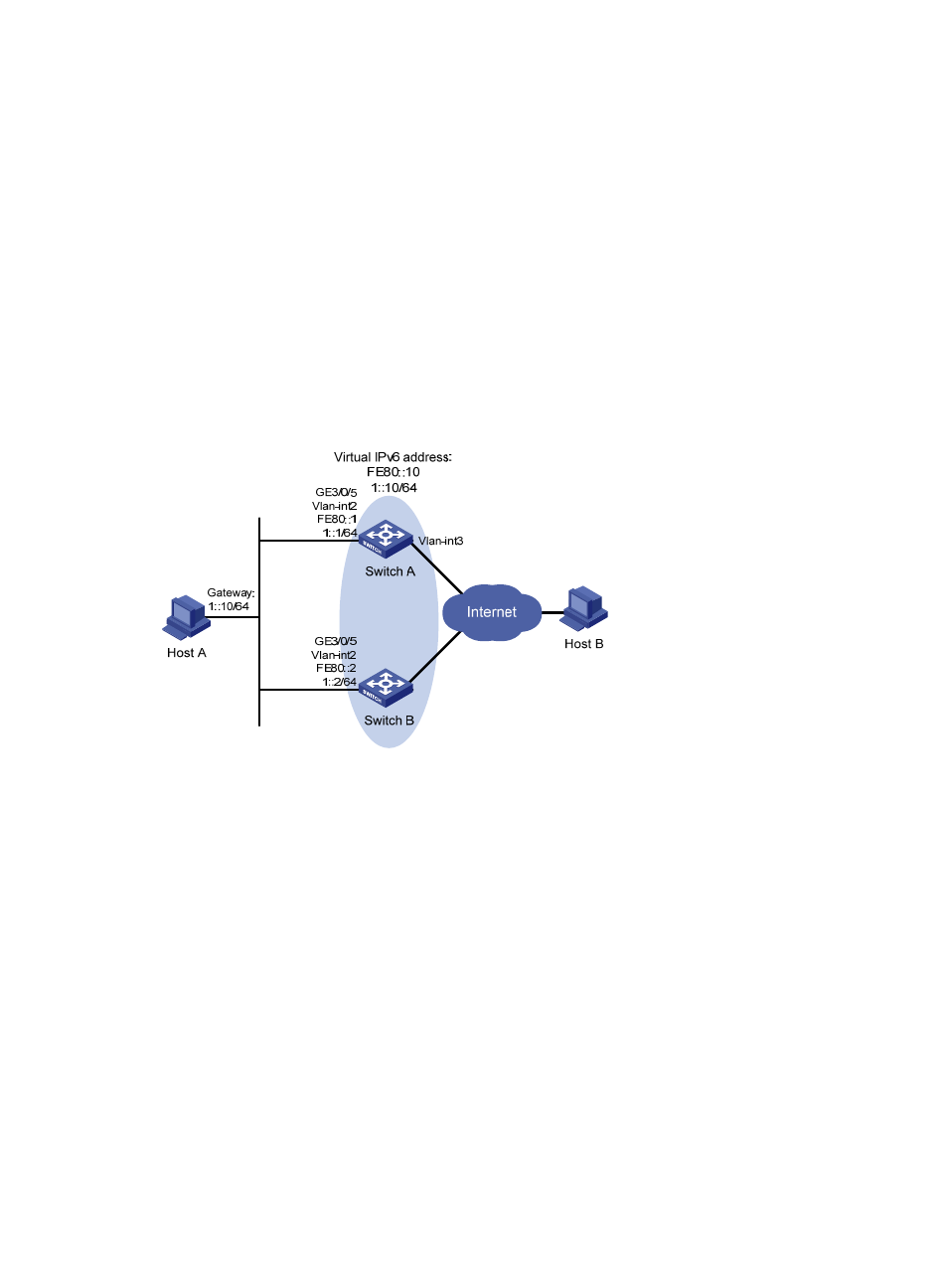
VRRP interface tracking configuration example
Network requirements
Switch A and Switch B belong to VRRP group 1 with the virtual IP addresses of 1::10/64 and FE80::10.
Host A wants to access Host B on the Internet, and learns 1::10/64 as its default gateway through RA
messages sent by the switches.
When Switch A operates correctly, packets sent from Host A to Host B are forwarded by Switch A. If
VLAN-interface 3 through which Switch A connects to the Internet is not available, packets sent from Host
A to Host B are forwarded by Switch B.
To prevent attacks to the VRRP group from illegal users by using spoofed packets, configure the
authentication mode as plain text to authenticate the VRRP packets in VRRP group 1, and specify the
authentication key as hello.
Figure 44 Network diagram
Configuration procedure
1.
Configure Switch A:
# Configure VLAN 2.
<SwitchA> system-view
[SwitchA] ipv6
[SwitchA] vlan 2
[SwitchA-vlan2] port Gigabitethernet 3/0/5
[SwitchA-vlan2] quit
[SwitchA] interface vlan-interface 2
[SwitchA-Vlan-interface2] ipv6 address fe80::1 link-local
[SwitchA-Vlan-interface2] ipv6 address 1::1 64
# Create a VRRP group 1 and set its virtual IPv6 addresses to FE80::10 and 1::10.
[SwitchA-Vlan-interface2] vrrp ipv6 vrid 1 virtual-ip fe80::10 link-local
[SwitchA-Vlan-interface2] vrrp ipv6 vrid 1 virtual-ip 1::10
# Set the priority of Switch A in VRRP group 1 to 110, which is higher than that of Switch B (100),
so that Switch A can become the master.
[SwitchA-Vlan-interface2] vrrp ipv6 vrid 1 priority 110