Network requirements, Configuration procedure – H3C Technologies H3C S7500E Series Switches User Manual
Page 195
12-14
The above output indicates that when BFD detects that Switch A fails, it notifies VRRP through the
track module to change the status of Switch B to master, without waiting for a period three times the
advertisement interval, so that a backup can quickly preempt as the master.
Configuring BFD for the VRRP Master to Monitor the Uplinks
Network requirements
z
As shown in
, Switch A and Switch B belong to VRRP group 1, whose virtual IP
address is 192.168.0.10.
z
The default gateway of the hosts in the LAN is 192.168.0.10.
z
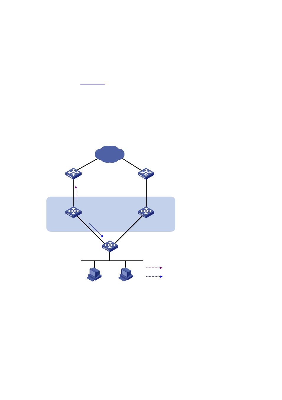
When Switch A works normally, the hosts in the LAN access the external network through Switch
A. When Switch A detects that the uplink is down through BFD, it decreases its priority so that
Switch B can preempt as the master, thus ensuring that the hosts in the LAN can access the
external network through Switch B.
Figure 12-4 Network diagram for monitoring uplinks using BFD
Internet
Master
uplink device
Backup
uplink device
Uplink
Virtual router
Virtual IP address:
192.168.0.10
Vlan-int2
192.168.0.101/24
Vlan-int2
192.168.0.102/24
Switch A
Master
Switch B
Backup
Vlan-int3
1.1.1.1/24
Vlan-int3
1.1.1.2/24
L2 switch
Uplink
VRRP packets
BFD probe packets
Configuration procedure
1) Create VLANs, and assign corresponding ports to the VLANs, and configure the IP address of
each VLAN interface as shown in Figure 12-4 . The configuration procedure is omitted.
2) Configure BFD on Switch A.
# Configure the source address of BFD echo packets as 10.10.10.10.
<SwitchA> system-view
[SwitchA] bfd echo-source-ip 10.10.10.10
3) Create a track entry to be associated with the BFD session on Switch A.
# Create track entry 1 to be associated with the BFD session to check whether the uplink device with
the IP address 1.1.1.2 is reachable.