Flood proxy configuration example, Network requirements – H3C Technologies H3C S6800 Series Switches User Manual
Page 74
66
MAC Table Limit : -
Drop Unknown : -
Flooding : Enabled
Statistics : Disabled
VXLAN ID : 10
Tunnels:
Tunnel Name Link ID State Type Flooding proxy
Tunnel1 0x5000001 Up Manual Disabled
Tunnel2 0x5000002 Up Manual Disabled
ACs:
AC Link ID State
FGE1/0/1 srv2 0 Up
# Verify that the VTEP has learned the MAC addresses of remote VMs.
<SwitchA> display l2vpn mac-address
MAC Address State VSI Name Link ID/Name Aging
cc3e-5f9c-6cdb Dynamic evpn2014 Tunnel1 Aging
cc3e-5f9c-23dc Dynamic evpn2014 Tunnel2 Aging
--- 2 mac address(es) found ---
2.
Verify that VM 1, VM 2, and VM 3 can ping each other. (Details not shown.)
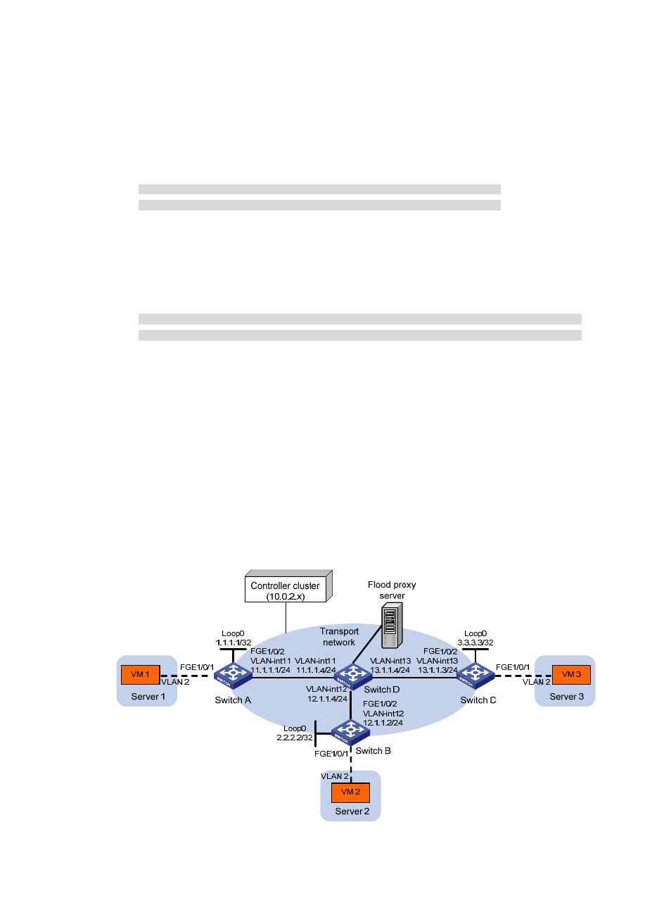
Flood proxy configuration example
Network requirements
As shown in
:
•
Configure the controller to deploy VXLAN 10 on Switch A, Switch B, and Switch C to provide Layer
2 connectivity for the VMs across the network sites.
•
Configure the controller to deploy remote MAC address entries to VTEPs.
•
Use a flood proxy server to forward inter-site flood traffic.
Figure 14 Network diagram