Configuration procedure – H3C Technologies H3C S5820V2 Series Switches User Manual
Page 25
19
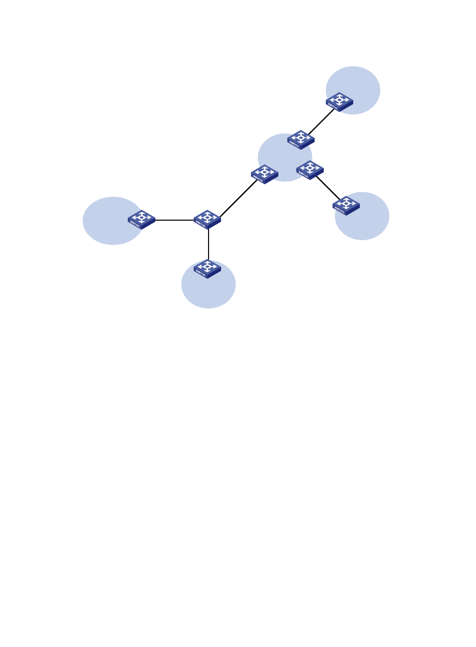
Figure 5 Network diagram
Configuration procedure
1.
Configure VPN instances.
Create VPN instances on the MCE and PE 1, and bind the VPN instances with VLAN interfaces.
For the configuration procedure, see "
Using OSPF to advertise VPN routes to the PE
."
2.
Configure routing between the MCE and VPN sites.
# Enable an OSPF process on the devices in the two VPNs and advertise the subnets. (Details not
shown)
# Configure OSPF on the MCE, and bind OSPF process 10 with VPN instance vpn1 to learn the
routes of VPN 1.
<MCE> system-view
[MCE] ospf 10 router-id 10.10.10.1 vpn-instance vpn1
[MCE-ospf-10] area 0
[MCE-ospf-10-area-0.0.0.0] network 10.214.10.0 0.0.0.255
[MCE-ospf-10-area-0.0.0.0] quit
[MCE-ospf-10] quit
# Display the routing table of VPN 1 on the MCE.
[MCE] display ip routing-table vpn-instance vpn1
Destinations : 13 Routes : 13
Destination/Mask Proto Pre Cost NextHop Interface
0.0.0.0/32 Direct 0 0 127.0.0.1 InLoop0
10.214.10.0/24 Direct 0 0 10.214.10.3 Vlan10
CE 2
VPN 1
Site 2
CE 1
VPN 2
Site 1
PE 1
PE 3
PE 2
VPN 2
192.168.10.0/24
VR 2
VPN 1
192.168.0.0/24
VR 1
MCE
XGE1/0/1
Vlan-int10
10.214.10.3/24
XGE1/0/1
Vlan-int30: 30.1.1.2/24
Vlan-int40: 40.1.1.2/24
XGE1/0/3
Vlan-int30: 30.1.1.1/24
Vlan-int40: 40.1.1.1/24
XGE1/0/2
Vlan-int20
10.214.20.3/24