Functional description – Grass Valley 2020DAC D-To-A User Manual
Page 26
20
2020DAC Instruction Manual
2020DAC 4-Channel Audio Digital to Analog Converter
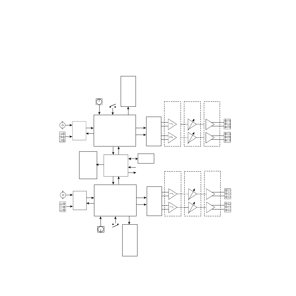
Functional Description
Refer to the block diagram in
while reading the following func-
tional description.
Note
As both CH 1/2 and CH 3/4 pairs are identical, only one channel description is
provided.
Figure 13. 2020DAC Block Diagram
8023_07
Sample
Rate,
Emphasis,
and
Remote
Override
LEDs
Comm,
Fault,
Config
and Power
LEDs
FPGA
Routing and Control
Processor
Frame
Communication
LPFs
Differential
Output
Drivers
Final Gain
Stage and
Z Matching
AES
Receiver
CH 1/2
INPUT
CH 3/4
INPUT
CPU
(Controller)
CH1/2 rotary
mode switch Option
jumpers
Stereo
24-bit
DAC
Clocks
Audio
Data
Sample
Rate,
Emphasis,
and
Remote
Override
LEDs
CH3/4 rotary
mode switch
Option
jumpers
75 Ohms
Unbalanced
110 Ohms
Balanced
CH 1
(Left) Out
CH 2
(Right) Out
FPGA
Routing and Control
Processor
LPFs
Differential
Output
Drivers
Final Gain
Stage and
Z Matching
AES
Receiver
Stereo
24-bit
DAC
Clocks
Audio
Data
75 Ohms
Unbalanced
110 Ohms
Balanced
CH 3
(Left) Out
CH 4
(Right) Out
FLASH
ROM