E illustrated in, Upon – Grass Valley 2031RDA-MM User Manual
Page 12
Advertising
12
2031RDA-SM/-MM Instruction Manual
Power Up
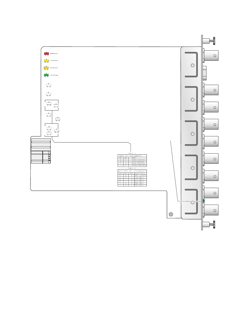
Figure 5. LEDs and Configuration Switches
8318_04
FAULT– (red) off during normal operation
COMM – (yellow)
CONF – (yellow)
PWR – (green) on during normal operation
Signal present – (green) on rear connector plate
SEE TABLE 1
M1
CD
LD
FAUL
T
COMM
CONF
PWR
REM
OVER
FIBER
SEL
M0
DR1
DR2
DR0
SEE TABLE 2
Advertising
This manual is related to the following products: