Power up, Operation indicator leds – Grass Valley 8920ADC v.2.0 User Manual
Page 11
8920ADC Instruction Manual
5
Power Up
Power Up
The front LED indicators and configuration switches are illustrated in
. Upon power-up, the green PWR LED should light and the yellow
CONF LED should illuminate for the duration of module initialization.
Operation Indicator LEDs
With factory default configuration and valid input and reference signals
connected, the green PWR LED and the green LOCK LED should be on.
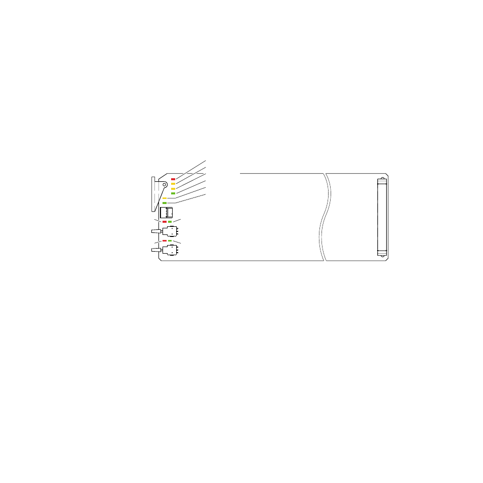
Figure 4. Operation Indicator LEDs
A red FAULT LED indicates an error situation and, with the other LEDs,
can indicate the operational conditions presented in
. The table
describes signal output and LED indications for various input/reference
combinations and user settings.
Left In
Clip (red)
Left In > -20dBFS (green)
Right In > -20dBFS (green)
Right In
Clip (red)
FAULT (red)
COMM (yellow)
CONF (yellow)
PWR (green)
REM OVER (yellow)
LOCK (green)
0595_06