Functional description, Digital input – Grass Valley 8920DAC User Manual
Page 23
8920DAC Instruction Manual
17
Functional Description
Functional Description
while reading the following func-
tional description.
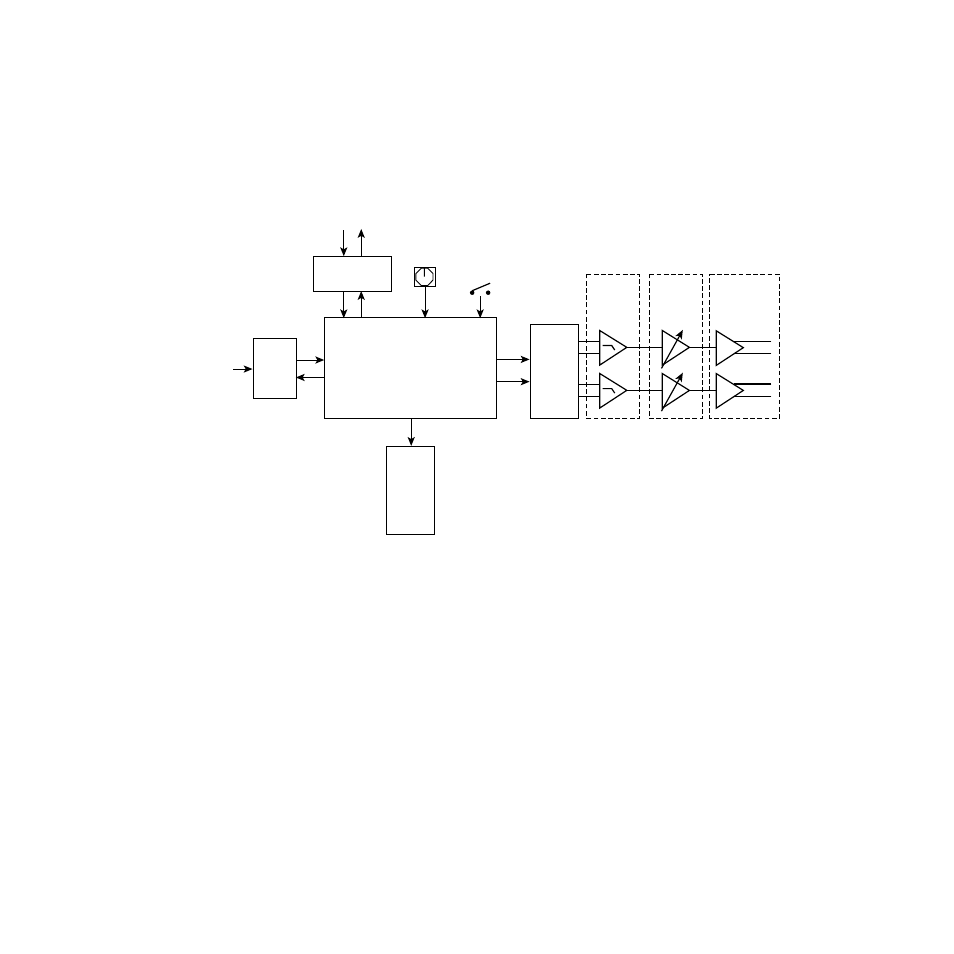
Figure 9. 8920DAC Block Diagram
Digital Input
AES/EBU audio data is fed into the 8920DAC through an isolation trans-
former to the receiver. The receiver extracts the audio signal (left/right), as
well as clock (bit clock, L/R clock and master clock), sample rate, emphasis
and error information. The signal, clock and other decoded information is
then passed to a FPGA (field-programmable gate array) for further
decoding and routing.
0614_01
–
–
+
+
Right Main
Left Main
Sample
Rate,
Error,
Emphasis,
and Mode
LEDs
FPGA
Routing and Control
Processor
Control bus
from back-plane
Differential
Input
Receivers
and LPFs
Differential
Output
Drivers
Final Gain
Stage and
Z Matching
AES/EBU
Receiver
Digital
Input
CPU
(Controller)
4-bit rotary
switch
Option
jumpers (4)
Stereo
24-bit
DAC
Clocks
Audio