Page 3 – Grass Valley 3e Student CameraMan Rev.B User Manual
Page 6
Advertising
Page 3
?
?
?
?
?
?
?
?
?
?
?
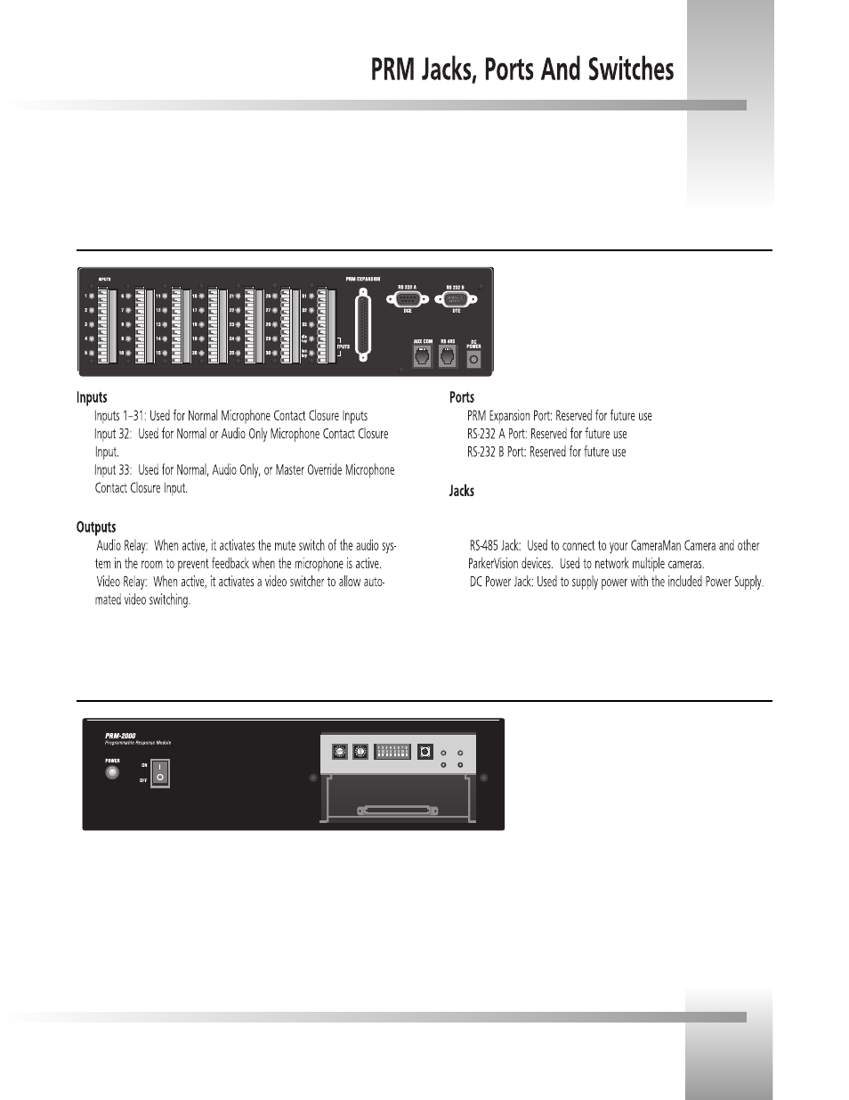
AUX COM Jack: Provides communications to select perpiherals
and provides capability for future expansion.
PRM Configuration Panel (front with plate removed)
PRM Jacks and Ports (back)
▼
Power Switch: Used Turn Power On.
▼
PRM Address Switch: 16-position rotary switch used to set the PRM
address which will reside on the RS-485 bus.
▼
Base Unit Address Switch: 16-position rotary switch used to tell the
PRM which camera it controls. It should match the Base Unit Address
switch on the CameraMan camera.
▼
DIP Switches: Used to configure the PRMs camera and microphone
control.
▼
Reset Button: Used to reset the PRM, but will not clear anycamera pre-
sets.
▼
Indicator Lights: Indicates communication activity.
Advertising