Multiple camera applications, Page 8 – Grass Valley 1-CCD CameraMan Rev.D1 User Manual
Page 11
Page 8
CameraMan® 1-CCD Camera Control Keypad Operations Manual
Multiple Camera Applications
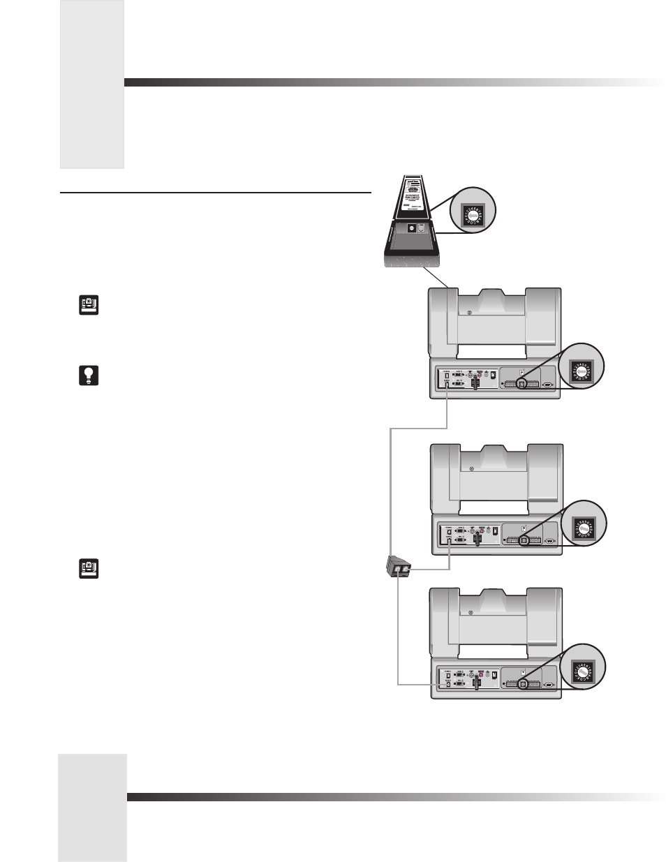
Multiple Camera Control (wireless and hard-wired combined mode)
In this mode, the keypad communicates with camera one (1) using RF (wireless). Any
commands sent to cameras two or three will be received by camera one and sent to the proper
camera using RS-485 communications. The keypad is NOT hardwired.
1. Make sure camera one is within 60 feet/18.28 meters of the keypad.
2. Make sure cameras two and three are daisy-chained to camera one.
See your 1-CCD CameraMan Installation and Operations Manual for more
information on daisy-chaining your cameras.
3. Set the KEYPAD ADDRESS on your Camera Control Keypad to match the BASE UNIT
ADDRESS on the first camera.
See page 3 for more information on setting the KEYPAD ADDRESS.
3. Set the BASE UNIT ADDRESS on the second and third cameras to successively
follow the address that you used for the first camera.
Example:
Camera Base Unit Address Keypad Address
1 0 0
2 1
3 2
5. Set the RF Command configuration switch on camera 1 to ENABLE (up). Set the RF
Command configuration switch on cameras 2 and 3 to DISABLE (down).
See your 1-CCD CameraMan Installation and Operations Manual for
more information on setting the configuration switches on your CameraMan
camera(s).
6. Set the Interlink configuration switch on Camera 1 to ON (up).
UP
DOWN
SWITCH BANK
-A-
1 2 3 4 5 6 7 8
UP
DOWN
SWITCH BANK
-A-
SWITCH BANK
-B-
1 2 3 4 5 6 7 8
1 2 3 4 5 6 7 8
S-VIDEO
COMPOSITE
BASE UNIT
ADDRESS
TALLY LIGHT
INTERFACE
UP
DOWN
SWITCH BANK
-A-
SWITCH BANK
-B-
1 2 3 4 5 6 7 8
1 2 3 4 5 6 7 8
S-VIDEO
COMPOSITE
BASE UNIT
ADDRESS
TALLY LIGHT
INTERFACE
T-Connector
Camera 2
Camera 3
Camera 1
SWITCH BANK
-B-
1 2 3 4 5 6 7 8
S-VIDEO
COMPOSITE
BASE UNIT
ADDRESS
TALLY LIGHT
INTERFACE
BASE UNIT
ADDRESS
BASE UNIT
ADDRESS
BASE UNIT
ADDRESS
BASE UNIT
ADDRESS
0
1
2 3
45 67
8
9
A
BC
DE
F
Back of Camera Control Keypad