2 installation – Grass Valley FOL-1601 User Manual
Page 7
GUIDE TO INSTALLATION AND OPERATION
FOL-1601 | 3
2 Installation
2.1 Unpacking
Make sure the following items have been shipped with your FOL-1601. If any of the following items are
missing, contact your distributor or Miranda Technologies Inc.
• FOL-1601 L-Band Fiber Receiver
• FOL-1601-SC-SRP Single Rear Panel (see figure 2.1)
2.2 Installation in the Densité frame
The FOL-1601 and its associated rear connector rear panel must be mounted in a DENSITÉ frame. It is not
necessary to switch off the frame’s power when installing or removing the card. See the DENSITÉ Frame
manual for detailed instructions for installing cards and their associated rear panels.
• NOTE: When you connect the optical fiber to the rear of the frame, the fiber plugs onto the card itself
and not the rear panel. Because a considerable amount of pressure is required to ensure a good
optical connection, the card must be firmly held in place to avoid being unseated. This is achieved by
using RF connectors between the rear panel and the card which require even more force to connect
and disconnect, thus preventing the card from moving when the optical fiber is connected.
• THEREFORE, be sure to press the FOL-1601 card FIRMLY into place when installing it, to be sure
that all connectors are properly mated.
2.3 Rear Panel Connectors
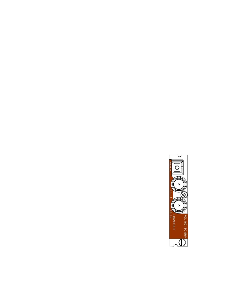
The FOL-1601 rear panel is shown in figure 2.1
The following connectors are found on this panel:
FIBER IN – optical input (SC/APC connector)
• Connect the input from the fiber link to this connector.
L-BAND OUT 1 – RF input (75
Ω F connector)
• Output broadband RF signal (950 MHz to 2150MHz).
L-BAND OUT 2 – RF monitoring output (75
Ω F connector)
• Output broadband RF signal (950 MHz to 2150MHz)
Figure 2.1 FOL-1601-SC-SRP Rear Panel