Cabling, Loop-through input, Outputs/inputs – Grass Valley 2000A89 User Manual
Page 12
6
2000A89 Instruction Manual
2000A89 Module Adapter Assembly
Cabling
The specific function of each 2000A89 BNC connector is determined by the
8900 module that is installed.
Loop-through Input
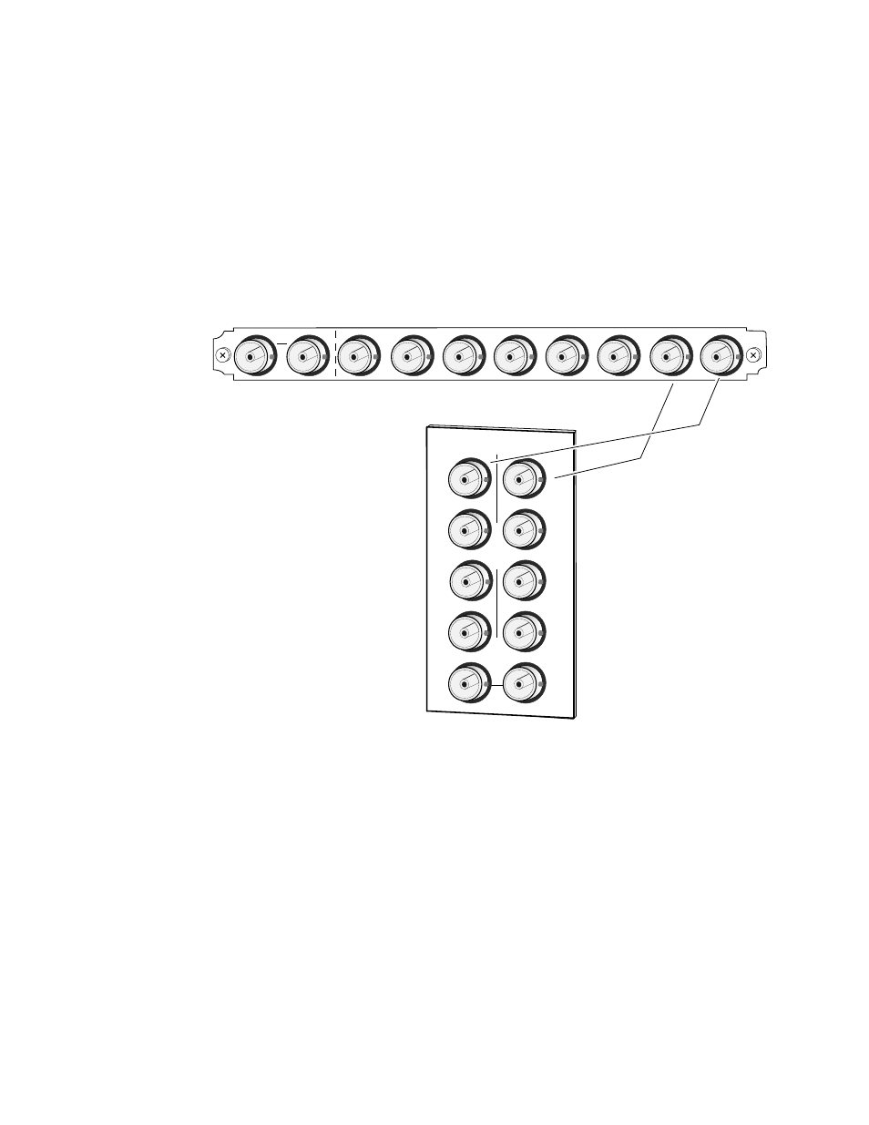
As in the 8900 frame, connectors J9 and J10 function as a loop-through
input connections (see
). Terminate the unused connector into 75
Ω
if the signal is not looped to other equipment.
Figure 5.
2000A89
Input/Output Connectors
Outputs/Inputs
The 2000A89 provides eight BNCs (J1 through J8) for direct (non-looping)
signal connections. The J numbers indicate the same wired connection to
the 8900 module as occurs in the 8900 frame rear connector.
IN
J10
J9
J8
J7
J6
J5
J4
J3
J2
J1
2000
A89
8030-02
J2
J4
J6
J8
J9 J10
IN
10
O
U
T
J3
J1
J5
J7
J2
J6
J4
J8
Connector J numbers
correspond to 8900
connector numbering
J1 to J1, J2 to J2, etc.