Figure 5 – Grass Valley Trinix Back-Up Power Supplies Nov 16 2012 User Manual
Page 43
Trinix — Installation and Service Manual
43
Installation Procedure - DV-33512 Units
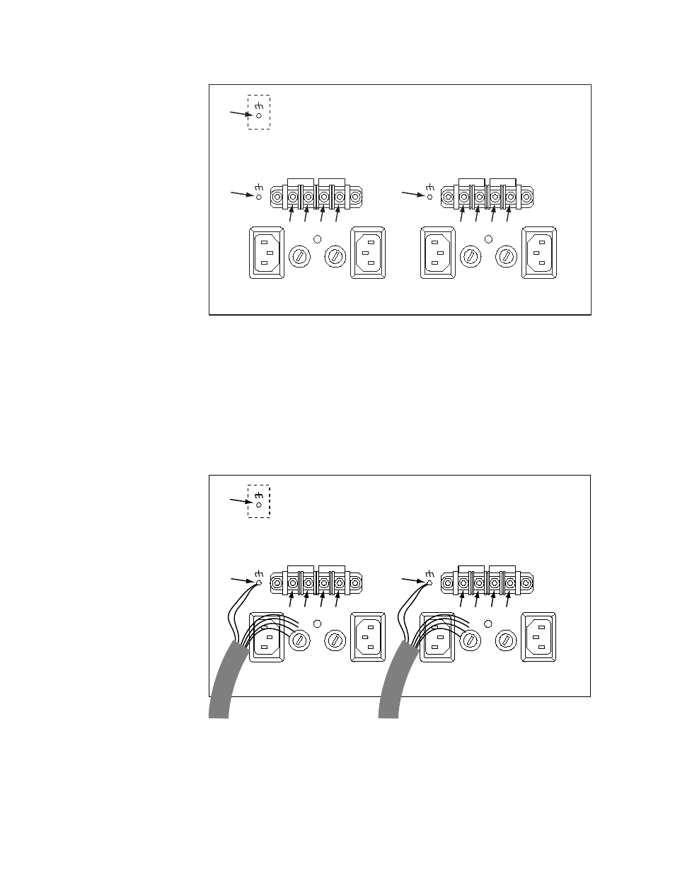
Figure 5. DV-33512 Power Supply Connectors Showing Reference Numbers Used in this Document
c.
Remove the “DC IN +” and “DC IN -” screws (3), (4), (5), (6), (8), (9),
(10), and (11).
d.
Locate the two DC power ground studs (2) and (7). Use a nut driver
to remove one nut (only) and one washer (only) from each stud.
e.
Connect the supplied jumper wires and external power supply
cables as shown in
and
Figure 6. Jumper and External Power Supply Wiring (Partially Complete)
DC IN -
DC IN +
PS B
PS A
DC IN -
DC IN +
PS D
PS C
(1)
(2)
(7)
(3)
(4)
(5)
(6)
(8)
(9)
(10) (11)
8443_03
DC IN -
DC IN +
PS B
PS A
DC IN -
DC IN +
PS D
PS C
(1)
(2)
(7)
(3)
(4)
(5)
(6)
(8)
(9)
(10) (11)
to external A/B power supply(s)
to external C/D power supply(s)
8443_16