4 connection unit, Example – Grass Valley RSE1 User Manual
Page 18
RSE 1
Stand-Alone Controller
13
Rev. 1 / 02.2002
3.4
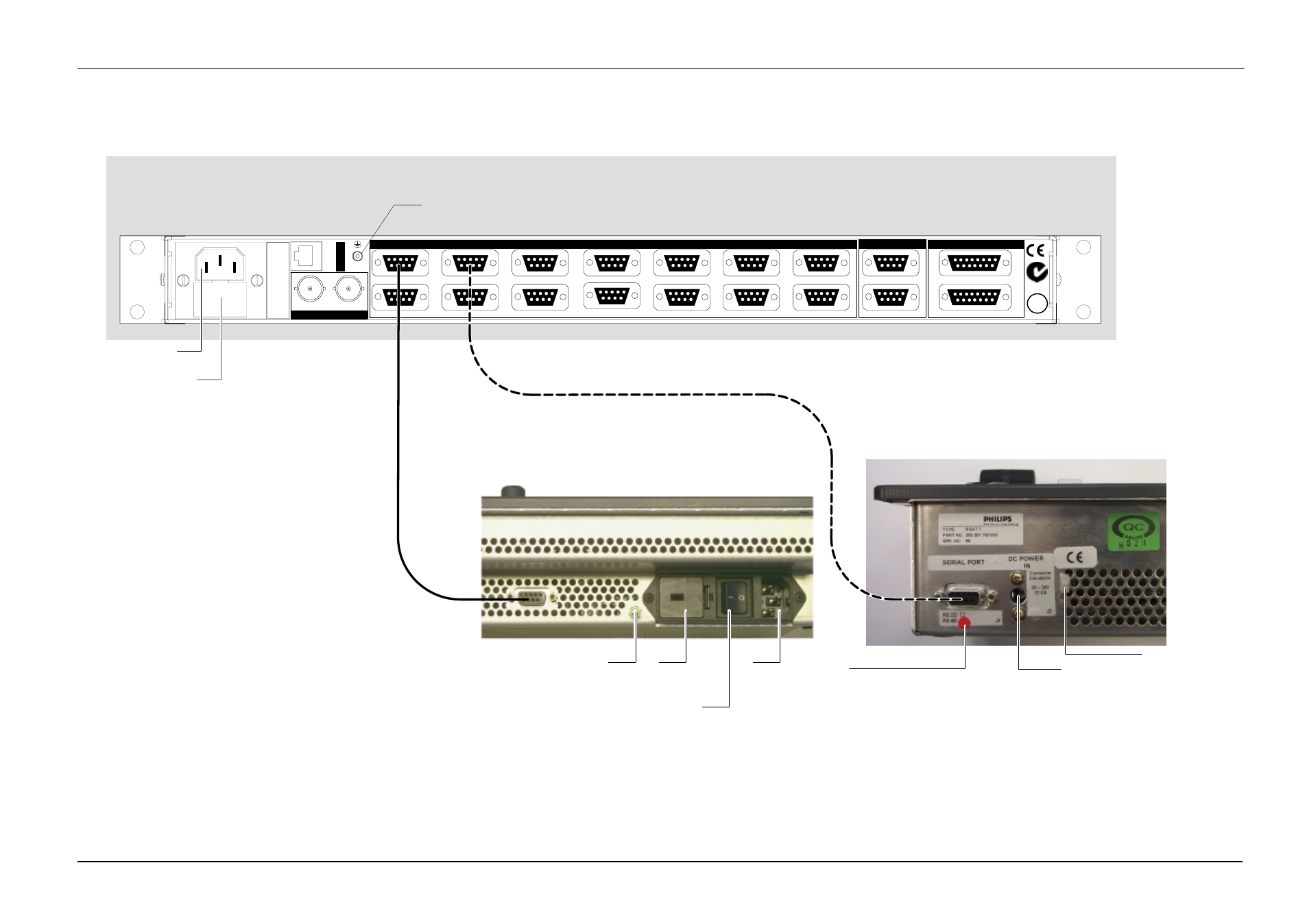
CONNECTION UNIT
Example:
J 20
J 21
J19
J 1
J 2
J 3
J 4
J 5
J 6
J 7
J 8
J 17
J 9
J 10
J 11
J 12
J 13
J 14
J 15
J 16
J 18
AUI
GP
Diagn
N4067
Genlock
PE
RS 485 / RS 422
RS 232
Stand-Alone Controller RSE 1
rear view
RS-485 / RS-422 Cable
(Option)
RS-485 / RS-422 Ports
AC IN
Fuses
Befor mounting the Satellite
Panel, switch to ON
Protective Earth
Fuses
AC IN
Protective Earth
Marker for port configuration
Factory setting: RS-422/RS-485
DC IN
any polarity
Fixture for DC cable
Remote Control Panel RSAT 2
rear view
Satellite Panel RSAT 1
rear view
J 22
LAN TP
AC POWER IN
100
–
240 V / max. 500mA
–
50/60 Hz
Caution:
For continued protection against risk of fire,
repplace only with same type and rating of fuse.
U T
RS-485 / RS-422 Cable
(Option)
Notes:
- It is only possible to connect one RSAT panel to the RSE1, either a RSAT1 panel or a RSAT2 panel.
- The panel software supports only the first four serial ports J1 ... J4, RS485, bus controller mode.
Fig. 2: Example RSAT assignment