SMA MULTIFUNCTION RELAY User Manual
Page 13
Advertising
SMA Solar Technology AG
4 Electrical Connection
Installation Manual
MFR-NR-IA-en-21
13
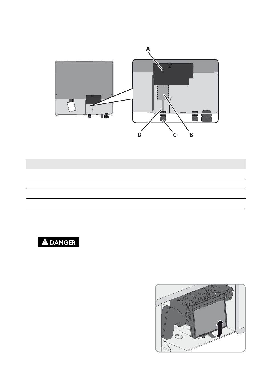
Mounting Position and Cable Route in the Sunny Boy / Windy Boy
Figure 5: Installation area and cable route in the Sunny Boy/Windy Boy with the lower enclosure lid open and
the display assembly flipped up
4.4.2 Installing the Multifunction Relay in the
Sunny Boy Smart Energy
2. Remove the display:
• Flip the display up.
Position
Designation
A
Inverter display assembly
B
Installation location of the multifunction relay
C
Cable route for the connection to the multifunction relay
D
M20x1.5 cable gland
1.
Danger to life due to high voltages in the inverter
• Disconnect the inverter from voltage sources and open the enclosure lid
(see inverter manual).
Advertising