6 electrical connection, 1 overview of the connection area, 1 components and terminals – SMA MULTICLUSTER BOX 12 User Manual
Page 17
SMA Solar Technology AG
6 Electrical Connection
Operating Manual
MC-BOX-12-3-20-BE-en-10
17
6 Electrical Connection
6.1 Overview of the Connection Area
6.1.1 Components and Terminals
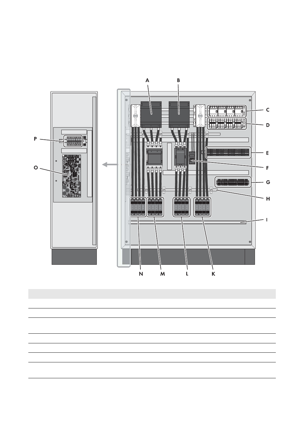
Figure 8: Overview of the connection area
Position
Designation
Explanation
A
Fuse switch-disconnector F101
For LV/HRC size 1 fuse links of the generator terminal
B
Fuse switch-disconnector F102
For LV/HRC size 1 fuse links of the load terminal
C
Residual-current device of the
Sunny Island inverters
‒
D
Circuit breakers
To protect the power cables of the Sunny Island inverters
E
Spring-cage terminals X105
To connect the power cables of the Sunny Island inverters
F
Grounding contactor
‒
G
Spring-cage terminals X106 - X113
To connect the control cables of Sunny Island inverters, BatFuse,
Grid Connect Box or NA Box