3 connecting the ripple control receiver – SMA POWER CONTROL MODULE User Manual
Page 15
SMA Solar Technology AG
5 Electrical Connection
Installation Manual
PWCBRD-10-IA-en-14
15
5. Fasten the module using the screw M4x10 and a
Torx screwdriver (T 20) (torque: 1.5 Nm).
5.3 Connecting the Ripple Control Receiver
Additionally required material (not included in scope of delivery):
☐ Ripple control receiver with at least three outputs
☐ One connection cable
Cable requirements:
☐ Cable cross-section: 5 mm to 13 mm
☐ Conductor cross-section: 0.5 mm² to 1.5 mm²
☐ Maximum cable length: 100 m
☐ Cables to be laid outdoors must be UV-resistant or routed in a UV-resistant cable channel.
☐ Required number of insulated wires for connecting the ripple control receiver: five insulated
wires
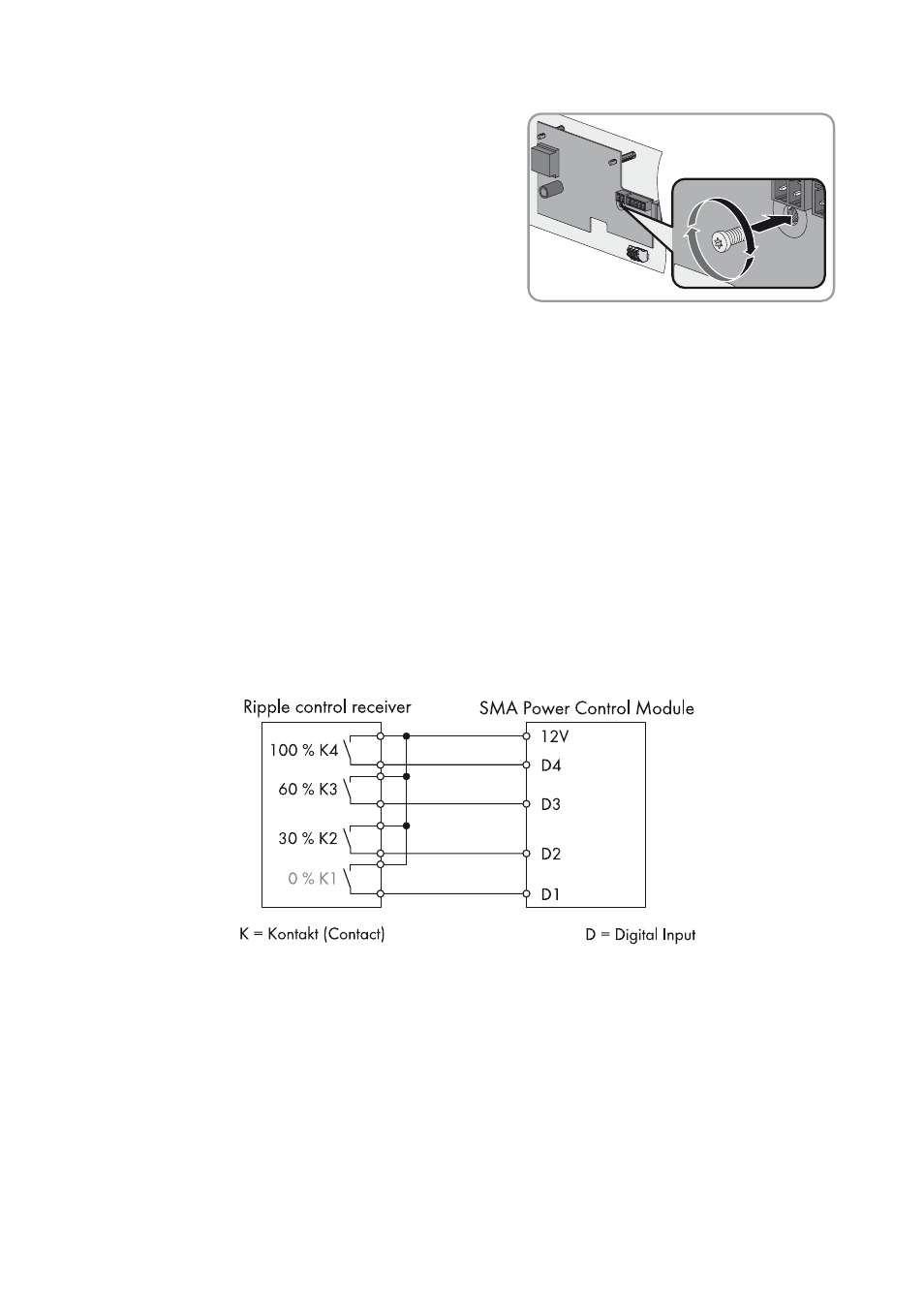
Figure 5: Wiring overview for a ripple control receiver with four relays (example)