SMA METER CONNECTION BOX User Manual
Page 16
Electrical Connection
SMA Solar Technology AG
16
METERBOX-IEN110611
Installation Guide
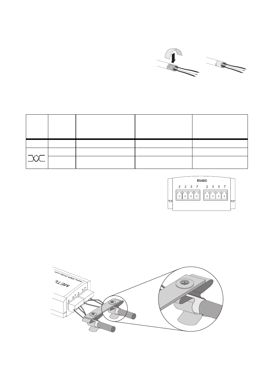
3. If the Meter Connection Box is in the center of the RS485 communication bus:
• Pull back the cable shield and cover with
conductive adhesive film. This is where the shield
clamp will be attached later.
4. Shorten the insulated conductors not required
down to the cable sleeve.
5. Strip approx. 6 mm off the wires.
6. Connect the insulated conductors to the 4-pole plug.
7. Write down the color of the insulated conductors.
8. Insert the plug in the Meter Connection Box in one
of the two terminals for the RS485 communications
bus.
9. Connect the other end of the cable to the RS485 communication bus.
See the RS485 cabling plan poster for the connection layout and system wiring.
10. If the Meter Connection Box is in the center of the RS485 communication bus:
• Push the shield clamp on the cable shield on both cables.
☑ The Meter Connection Box is now connected to the RS485 communication bus.
Symbol Signal
Meter Connection Box
Terminal for the RS485
communication bus
Insulated conductor
color
RS485
communication bus
GND
5
5
Data+
2
2
Data −
7
7