Voltage vs freq, Spl vs freq – JBL Synthesis Everest DD67000 User Manual
Page 19
37
36
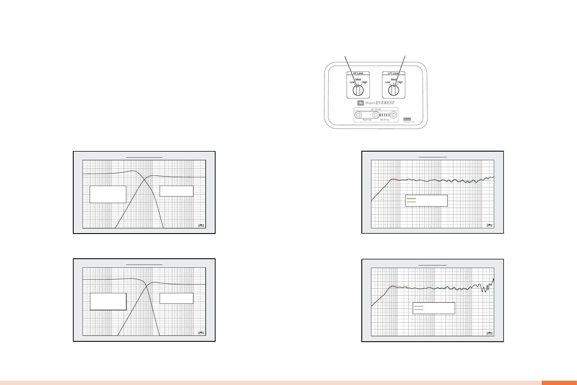
hF And LF1 LeveL swiTches
high-frequency
Level switch
Lf1 Woofer
Level switch
The HF Level switch adjusts the attenuation applied to the
476-series high-frequency transducer by approximately ±0.4dB
over the range of 1,000Hz to about 8,000Hz. The action is
accomplished by trimming the main attenuation resistors.
Midrange sound becomes softer by reducing the level and
stronger by increasing the level. No additional parts are inserted
in the signal path and there is no sonic deterioration by position or
adjustment functions.
There is also a level trim switch available for the LF1 woofer. LF1
is the low-range woofer (that operates up to 150Hz), and each
position will affect the output level in the range of 40Hz to 120Hz
by about ±0.5dB. The purpose of this adjustment is to allow fine-
tuning of the bass to mid-bass response of the system to better
integrate with different room characteristics. The adjustment is
accomplished by a change in value of a parallel damping resistor in
the LF1 woofer circuit. No insertion loss is caused by this control.
Setting the LF- and HF Drive shorting bars in the Bi-Amp position
bypasses the speaker’s crossover function for the full-range woofer
and the high-frequency driver. The low-frequency woofer and the
ultrahigh-frequency drivers are unchanged. Setting the shorting
bars in the Bi-Amp position requires the addition of an external
dividing network (electronic crossover) to provide the 750Hz
(DD65000) or 850Hz (DD67000) primary crossover point for the
system. The built-in attenuation and equalization for the 476-series
high-frequency driver remains in place. The high-frequency level
trim control remains operational, as does the diode biasing for both
the low-frequency and high-frequency network sections.
Normally, all three sets of shorting bars (two LF and one HF)
would be moved together to set the loudspeaker for bi-amping.
It is possible to operate the system with just the low-frequency
system or the high-frequency system set for bi-amping. In this
circumstance, it would be necessary to use a combination of an
external dividing network and the internal network. However, this
is not generally recommended.
The graphs below shows the low-frequency and high-frequency
voltage drive functions necessary to properly bi-amplify a
DD65000 or DD67000 system using an external dividing network
and two amplifier channels. Neither the low-pass nor the high-
pass drive is a standard Butterworth alignment or, for that matter, a
standard alignment at all. The provided drive curves were derived
using the internal passive network and resulting acoustic low-pass
and high-pass shapes. Duplicating these shapes will result in the
same frequency response and directivity pattern as the passively
driven system. The low-pass section is made up of two cascaded
second-order sections and the high pass is a single high-pass
section. The values within a high-quality analog dividing network
can usually be modified to achieve these results. Recent digital
crossover units will have no problem duplicating these curves.
20Hz
50
100
200
500
1k
2k
5k
10k
20k
dBm
-30
-25
-20
-15
-10
-5
0
5
10
Voltage vs Freq
24 dB/Oct
LP1: Fo = 430 Hz, Q =1
LP2: Fo = 1100 Hz, Q = 1.4
Gain = 2 dB
12 dB/Oct
HP: Fo = 700 Hz, Q = 0.94
DD65000 Voltage Drive
20Hz
50
100
200
500
1k
2k
5k
10k
20k
dBm
-30
-25
-20
-15
-10
-5
0
5
10
Voltage vs Freq
24 dB/Oct
LP1: Fo = 440 Hz, Q =0.71
LP2: Fo = 700 Hz, Q = 1.8
Gain = 3 dB
12 dB/Oct
HP: Fo = 800 Hz, Q = 1.0
DD67000 Voltage Drive
20Hz
50
100
200
500
1k
2k
5k
10k
20k
dBSPL
60
65
70
75
80
85
90
95
100
105
110
SPL vs Freq
= LF1 Adjustment Range
= HF Adjustment Range
DD65000 Control Adjustment Range
20Hz
50
100
200
500
1k
2k
5k
10k
20k
40k
dBSPL
60
65
70
75
80
85
90
95
100
105
110
SPL vs Freq
= LF1 Adjustment Range
= HF Adjustment Range
DD67000 Control Adjustment Range