Chapter 3, Board layout, Sct1 – Lanner LVC-5000(N4) User Manual
Page 17
17
Board Layout
Chapter 3
Embedded and Industrial Computing
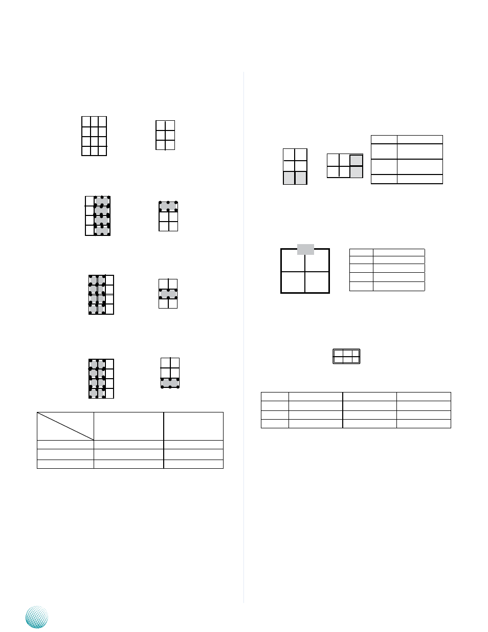
SCT1, SCT2: Select COM2 Protocol Setting
RS-232
RS-422
RS-485
Switch
Protocol
SCT1
SCT2
RS-232 (default)
1-5, 2-6, 3-7, 4-8
1-2
RS-422
5-9, 6-10, 7-11, 8-12
3-4
RS-485
5-9, 6-10, 7-11, 8-12
5-6
12
11
10
9
4
3
2
1
SCT2
2
4
6
1
3
5
SCT1
4
3
2
1
12
11
10
9
1
2
PCOM1, PCOM2: Select COM1 and COM2 Pin9 Function
(in RS-232) respectively. The Ring indicator pinout of
the RS-232 COM port can be altered according to the
following jumper settings.
PS4M1: Connect to the ATX1 power connector on the
LVK-POE60W01 board
AUDIOIN1: Line-in and Mic-in Connector
Pin No.
Function
1-2
Supply +5V to
the Device
3-4
Supply +12V to
the Device
5-6
Ring-in (default)
2 4 6
PCOM1
2
4
6
1
3
5
1 3 5
PCOM2
Pin No.
Pin Name
1
GND
2
DC_VIN (9-36V)
3
GND
4
DC_VIN (9-36V
2 1
4 3
Pin No.
Pin Name
Pin No.
Pin Name
1
MIC_in_R
2
MIC_in_L
3
Audio_in_R
4
Audio_in_L
5
Line_in1_R
6
Line_in1_L
1 3 5
2 4 6