Motherboard layout, Chapter 3, Motherboard information – Lanner FW-7610 User Manual
Page 11
Advertising
8
Motherboard Information
Chapter 3
Network Application Platforms
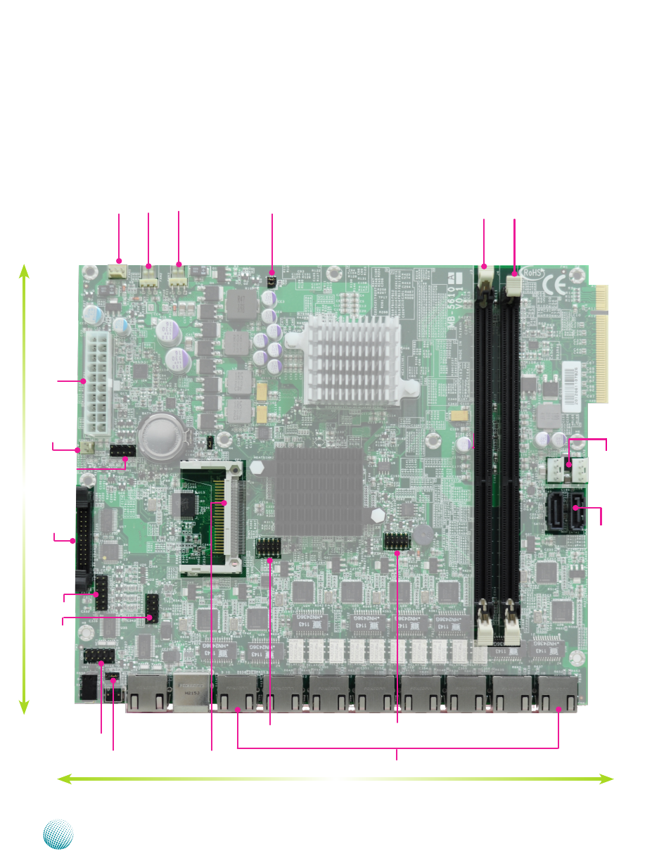
Motherboard Layout
The motherboard layout shows the connectors and
jumpers on the board. Refer to the following picture
as a reference of the pin assignments and the internal
connectors.
RJ45 Console Port
Low-Pin Count
Connector
(LPC1)
ATX Power
Connector(ATX1)
SATA Power Connector
(PWR1/PWR2)
DIMM Slot (J3)
220mm
190mm
FAN2
Power
Connector(CONN1)
Keyboard and
mouse (KBMS1)
SATA Port (SATA2/
SATA1)
FAN3
FAN1
VGA Connector
(J6)
USB Connector
(J7)
Serial Interface
(COM1)
CMOS Reset
(JP1))
CompactFlash
(CF1)
RJ45 Console Port
Serial Peripheral
Interface Bus
(SPI1)
DIMM Slot (J4)
J13
LCM (LCM1)
Advertising