Motherboard layout, Chapter 3, Motherboard information – Lanner MR-301 User Manual
Page 11
Advertising
8
Motherboard Information
Chapter 3
Network Application Platforms
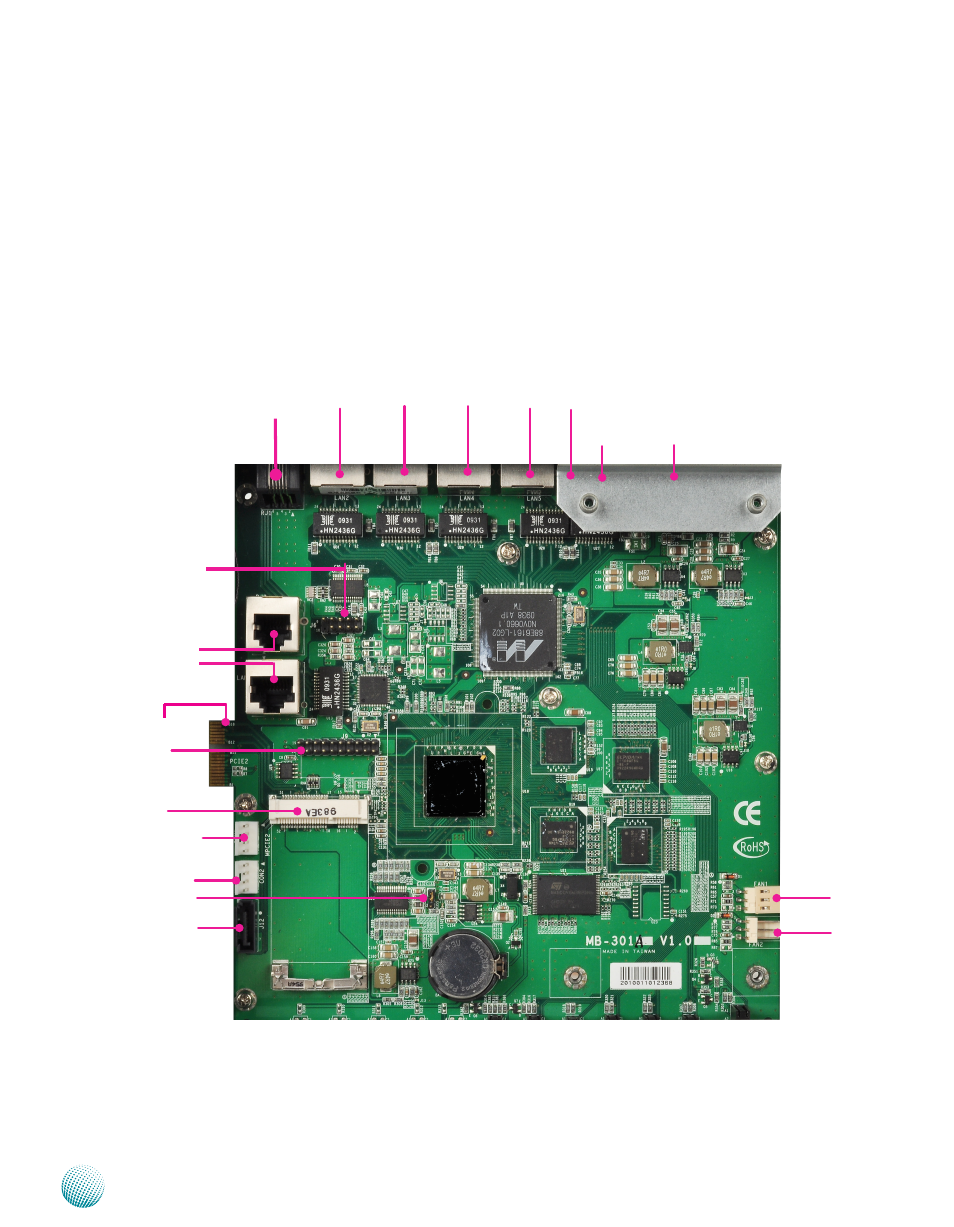
Motherboard Layout
The motherboard layout shows the connectors and
jumpers on the board. Refer to the following picture
as a reference of the pin assignments and the internal
connectors.
JTAG(J9)
FAN1
LINE Port
(RJ1)
Mini PCI-E
connector(MPCIE2)
SATA Power
Connector
(CON1)
SATA Power
Connector (CON2)
SATA Connector
(J12)
PCI-E x1 Golden Finger
(PCIE2)
GPIO Connector
(J14)
DSL module LAN Con-
nector (LAN7)
DSL module RJ11
Connector (RJ2)
Serial Port UART1 (J6)
Connector
USB Connector
(J2)
Console Port UART0
(LAN1)
LAN Port 4
(LAN3)
L A N P o r t 5
(LAN2)
LAN Port 3
(LAN4)
LAN Port 2
(LAN5)
LAN Port 1
(LAN6)
FAN2
Advertising