Chapter 3, Motherboard information, Power ignition board layout- top view – Lanner VES-500 User Manual
Page 11: Power ignition board layout-bottom view
Advertising
11
Motherboard Information
Chapter 3
Embedded and Industrial Computing
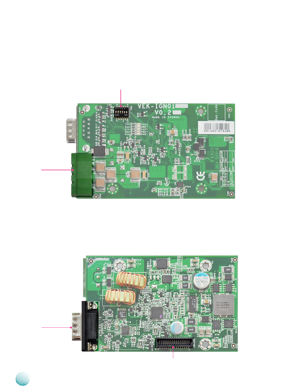
Power Ignition Board Layout- Top View
The motherboard layout shows the connectors and
jumpers on the board. Refer to the following picture and
table 3.2 as a reference of the pin assignments and the
internal connectors.
PRJK1
SW1
VEK-IGN01
Power Ignition Board Layout-Bottom View
The motherboard layout shows the connectors and
jumpers on the board. Refer to the following picture and
table 3.2 as a reference of the pin assignments and the
internal connectors.
DGIO1
IGNI01
Advertising