Front components, Chapter 2, System components – Lanner LEC-7050 User Manual
Page 9
8
System Components
Chapter 2
Embedded and Industrial Computing
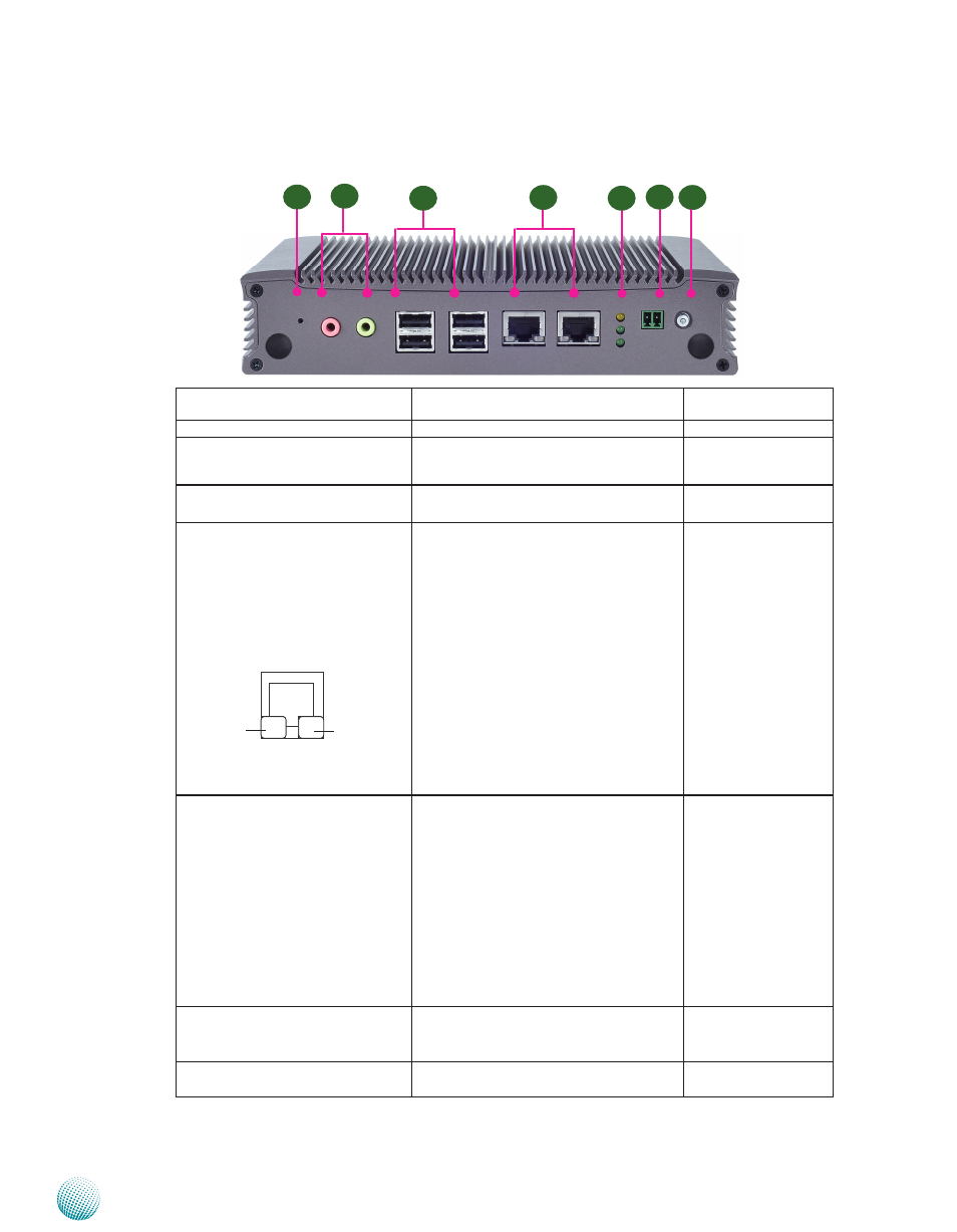
Front Components
sPEEd
LINK/ACT
F2
F6
F3
F5
F4
F1
F7
Component
Description
Pin Definition
Reference
F1 Reset
Reset switch
SW5 on page 15
F2 MIC IN/LINE OUT
Connect the audio devices to these ports.
The Microphone and line out port are
provided by Realtek ALC
886.
J3, J4 on page 13
F3 Four USB 2.0 Ports
An USB type A connector.
USB1, USB2 on Page
15
F4 Two 10/100/1000Mbps LAN ports Two RJ-45 (network) jacks with LED
indicators as described below. Both LAN
ports are provided by Intel 82583V. The
82583V supports PXE remote boot
LINK/ACT (Yellow)
On/Flashing: The port is linking and
•
active in data transmission.
Off: The port is not linking.
•
SPEED (Green/Amber)
Amber: The connection speed is
•
1000Mbps.
Green: The connection speed is
•
100Mbps
Off: The connection speed is 10Mbps.
•
LANB1/LANB2 on
page 14
F5 HDD (Yellow)
Status and
Power LED (Green)
HDD
Blinking: data access activities
•
Off: no data access activities
•
Status
A programmable dual green/orange LED
which can be used for indicating system
status.
Power
On: The computer is on.
•
Off: The computer is off .
•
F6 Power-on Switch
A power-on switch through the Phoenix
contact for distant power-on/off control
CN4 on page 15
F7 Power Button with dual LED
ATX Power-on button with LEDs: Standby
mode in Red; Power-on mode in Green
U45 on page 15