Jumper settings, Chapter 3, Board layout – Lanner LEC-7070 User Manual
Page 13
13
Board Layout
Chapter 3
Embedded and Industrial Computing
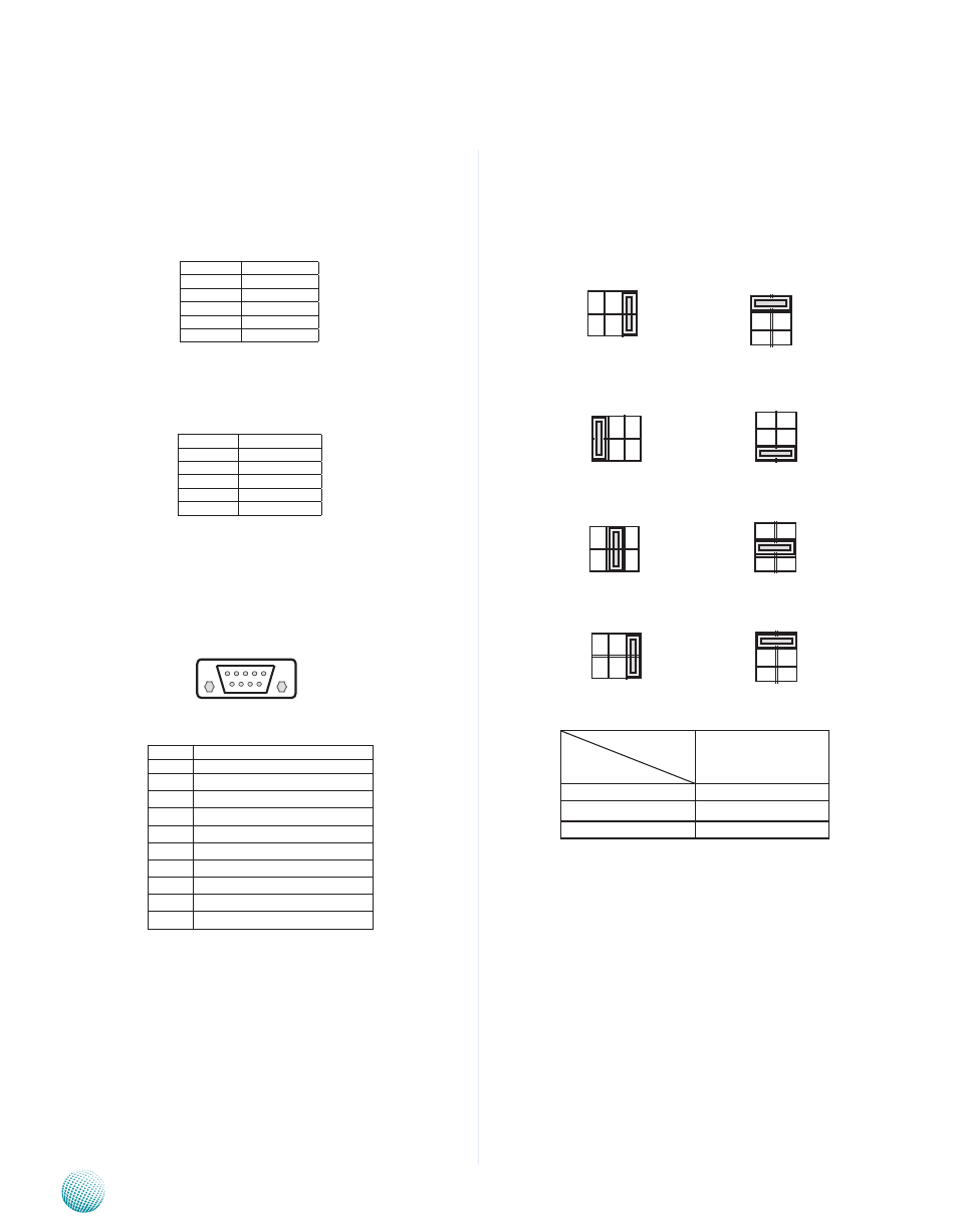
Select COM1/COM2 Pin 9 Function (SC1T1/SC2T1): The
pin 9 of COM1 and COM2 can be altered by SC1T1 and
SC2T1 respectively according to the following jumper
settings.
+5V
+12V
RI
Jumper Setting
Function
SW1/SW4
+5V
1-2
+12V
3-4
RI#
5-6
Jumper Settings
Microphone-in Audio Jack (MIC1)
Line-out Audio jack (LIN1)
RS-232 Serial Port (COM1 and COM2): It is a RS-232
port through a D-SUB9 connector.
Pin No.
Function
1
GNd
2
MIC_L
3
GNd
4
GNd
5
MIC_R
Pin No.
Function
1
GNd
2
LINE_OUT_L
3
GNd
4
GNd
5
LINE_OUT_R
Pin No.
Pin Name
Rs-232
1
data Carrier detect ( dCd # )
2
Receive data ( RXd )
3
Transmit data ( TXd )
4
data Terminal Ready ( dTR # )
5
Ground ( GNd )
6
data set Ready ( dsR # )
7
Request To send ( RTs # )
8
Clear To send ( CTs # )
9
Ring Indicator ( RI # )
SC1T1: COM1
SC2T1: COM2
6 7 8 9
1 2 3 4 5
1 3 5
2 4 6
5
3
1
6
4
2
1 3 5
2 4 6
2 4 6
5
3
1
6
4
2
5
3
1
6
4
2
2 4 6
1 3 5
5
3
1
6
4
2