Linkskey LKV-E412 User Manual
Quick installation guide, Cat5 usb kvm extender lkv-e412
Quick Installation Guide LKV-E412 CAT5
5
5
5 USB KVM Extender Set
1
Rev. 1.1 Copyright© All rights reserved.
INSTALLATION
Quick Installation Guide
CAT5 USB KVM Extender
LKV-E412
Built-in KVM Switching on the
Remote Console for More Versatility
Thank you for purchasing the LKV-E412 CAT5 USB KVM Extender
Set! The CAT5 USB KVM Extender Set comprises two units – one
Transmitter (Tx) Unit and one Receiver (Rx) Unit. With our highly
reliable and quality product, users can enjoy countless benefits
from using it.
INTRODUCTION
The LKV-E412 CAT5 USB KVM Extender Set – extends your
keyboard, mouse, and monitor from your computer up to 100M
(328ft) away on a single CAT5 UTP cable, with satisfying video
quality.
The CAT5 USB KVM Extender Set comprises two distinct units -
The Receiver (Rx) Unit and the Transmitter (Tx) Unit. The Tx Unit
and the Rx Unit will be located each on one end of the CAT5 UTP
cable. The Transmitter allows user to access the computer at the
local end, while extending it across 100M(328ft) to the Remote
console on the Receiver, which can therefore access and control
the extended computer as well as another computer in proximity of
the Receiver, due to a built-in KVM Switching feature into the
Receiver.
It is especially useful for setting up a highly flexible computer/user
topology over a sizable distance up to 100M(328ft) away.
Applicable either over an exhibition room, work floor, security room,
locked server room, or other mission-critical scenarios, the CAT5
USB KVM Extender Set allows you to locate your server physically
far back from the user due to security or spatial concerns. And it
allows the user to manage and control the computer at both
locations, and with the capability of switching between the original
computer and a second computer on the Receiver end.
PACKAGE CONTENTS
Please check whether you have all the following items within the
packaging box:
Transmitter (Tx) Unit x 1
Receiver (Rx) Unit x 1
Slim 3-in-1 PS/2 & USB KVM Combo-free Cable x 2
Power Adapters (DC5V / 2.0A) x 2
This Quick Installation Guide x 1
FRONT - PANEL & BACK - PANEL VIEW
The front and back panels are where the various connectors are
located on the two pieces of the CAT5 USB KVM Extender Set.
Before you connect these two units to any computer, cabling
accessories or peripherals, you should get a glimpse of the main
connectors you are going to encounter when setting up the system.
Transmitter (Tx) Unit – Front Panel
Transmitter (Tx) Unit – Back Panel
Transmitter Unit (Local End Connection)
[Tx – Front Panel]
a. Power LED (ON: Power on / OFF: Power off)
b. Link LED (ON: Link OK / OFF: No Link)
c. Console USB keyboard connector (USB Type A)
d. Console USB mouse connector (USB Type A)
e. Mode Select button for selecting Receiver Unit access mode
(Full Access / View Only / Access Deny)
f.
Video LED (ON: Remote video on / OFF: Remote video off)
g. Control LED (ON: Remote K/B & Mouse control enable / OFF:
Remote K/B & Mouse control disable)
[Tx – Back Panel]
h. Power jack (DC 5V, center-positive)
i.
Remote I/O port (RJ-45, connect to the Receiver Unit via a
CAT5 UTP cable, 100M/328ft max.)
j.
Computer port (HDB-15, connect to the local computer using a
special 3-in-1 KVM Combo-free cable)
k. Upgrade port (USB Type B, dedicated for firmware upgrade
use)
l.
Console video port (HDB-15, connect to monitor)
Receiver (Rx) Unit – Front Panel
Receiver (Rx) Unit – Back Panel
Receiver Unit (Remote End Connection)
[Rx – Front Panel]
1. Power LED (ON: Power on / OFF: Power off)
2. Link LED (ON: Link OK / OFF: No Link)
3. Console USB keyboard connector
4. Console USB mouse connector
5. Select toggle button for switching Local / Remote computer
6. Local LED (ON: Local computer active / OFF: Local computer
inactive)
7. Remote LED (ON: Remote computer active / OFF: Remote
computer inactive)
[Rx – Back Panel]
8. Power jack (DC 5V, center-positive)
9. Remote I/O port (RJ-45, connect to the Transmitter Unit via a
CAT5 UTP cable, 100M/328ft max.)
10. Computer port (HDB-15, connect to the local computer using a
special 3-in-1 KVM Combo-free cable)
11. Upgrade port (USB Type B, dedicated for firmware upgrade
use)
12. Console video port (HDB-15, connect to monitor)
Before you install the two pieces of the CAT5 USB KVM Extender
Set, you should have these items on the checklist ready:
1. The computer for extension should be one with USB
interfaces.
2. You should check the display mode of the computer to be
within 1600 x 1200 pixel dimension. And refresh rate to be one
that is more commonly used such as 60Hz, etc.
3. Prepare two sets of keyboard, mouse, monitor - one set for TX
Local console and the other set for RX Remote console.
4. The two monitors (one on the Tx side and the other on the Rx
side) used for display should be of the same resolution, and
better of the same type, same made and model.
5. Since the CAT5 USB KVM Extender Set supports only
standard 5-button mouse and keyboard, any more advanced
mouse / keyboard function will not be supported.
6. Use good quality CAT5 UTP cable, 100M(328ft) max.. Note
that better quality cable will give better video outcome with
longer distance span.
7. Any cabling distance longer than 100M(328ft) will experience
more signal degradation with longer span. However, better
quality cable can reach out farther away.
8. The choice of path of the CAT5 UTP cable should not only
take into account the shortest possible path, but also consider
any significant electromagnetic may interference source
factors too.
9. There should be power outlets near where you locate the
CAT5 USB KVM Extender Set.
Take the package items out of the box and begin installation
.
Plan the Layout Path and Deploy the UTP Cable for Extension
1. Plan the path through which the CAT5 UTP cable will be
deployed across the distance between the Transmitter and the
Receiver. You should choose the layout path not only base on
shortest be deployed across the possible length consideration,
but also on least electromagnetic interference.
2. Lay out the CAT5 UTP cable according to your planned path.
Configuring the Transmitter Console
3. Connect one end of the CAT5 UTP cable to the Remote I/O
port (connector
i) of the Transmitter.
4. Connect the AC power adapter to the power jack (connector
h)
of the Transmitter to power it up before connecting any
devices to it.
5. Connect the computer to the Computer port (connector
j) of
the Transmitter, using the 3-in-1 KVM Combo-free cable.
6. Connect a keyboard, mouse, and monitor to the Transmitter’s
Console ports (connector
c, d, and l).
7. Power on the computer and check the keyboard, mouse, and
video are working fine, and then go to the next step.
Configuring the Receiver Console
8. Connect the other end of the CAT5 UTP cable from the
Transmitter to the Receiver’s Remote I/O port (connector
9).
9. Connect the AC power adapter to the power jack (connector
8)
of the Receiver to power it up before connecting any devices
to it.
10. Connect a keyboard, mouse, and monitor to the Receiver’s
Console ports (connector
3, 4, and 12).
11. Switch to Remote by using Select button then check the
keyboard, mouse, and monitor are working fine. At this time,
the video might be blurred since it is not yet adjusted and
optimized.
12. Adjust the video parameters to optimize the display output
(Refer to OSD Menu / Video Setting section for details).
13. Connect the computer to the Computer port (connector
10) of
the Receiver, using the 3-in-1 KVM Combo-free cable.
14. Switch to Local by using Select button then power on the
computer and check the keyboard, mouse, and video are
working fine.
Now, you have set up the whole system and can operate
immediately ….
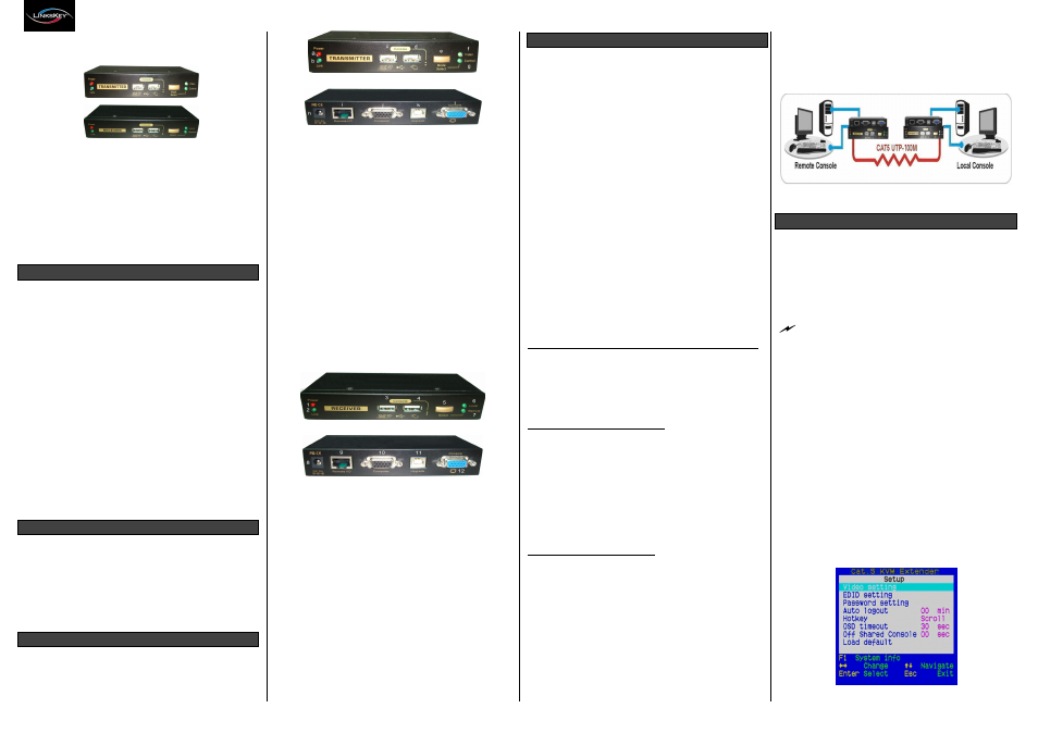
LKV-E412 CAT5 USB KVM Extender Configuration Diagram
OPERATION
On the Receiver Unit, the OSD (On-Screen Display) Menu control
is available to facilitate more intuitive operations. Users can
configure various settings by the OSD Menu.
OSD Menu (Only Available on Receiver Unit)
To evoke the OSD Menu, you should hit the following keyboard
hotkeys:
Hotkey sequence = [Scroll Lock] + [Scroll Lock] + [Space Bar]
Each keystroke within a hotkey sequence should be pressed
within 2 seconds. Otherwise, the hotkey sequence will not be
validated.
To navigate the OSD Menu, just use the following keys:
Esc: Exit
Left/Right cursor: Change value in the menu option
Up/Down Cursor: Navigate
F10: Log out the OSD Menu (However, if the password
protection is not enabled, the Logout feature will not be
available.)
These keys are listed explicitly on the OSD setting page for your
ready reference.
OSD Main Page
This is the OSD main menu and it is the first page you will see
when you hit the keyboard hotkeys - [
Scroll Lock] + [Scroll Lock]
+ [Space Bar] - to evoke the OSD Menu. (The default keyboard
hotkey is [Scroll Lock])
Note: There are two methods to setup the keyboard hotkeys
1. OSD Menu (Only available on Receiver Unit)
2. Keyboard (Only available on Receiver Unit)
Main Menu