Pin assignments, Pin descriptions, Pcb footprint – Linx Technologies EVM-915-250 User Manual
Page 5: Pin assignments pin descriptions
–
–
–
–
4
5
1
2
3
4
5
6
7
8
9
10
11
12
24
23
22
21
20
19
18
17
16
15
14
13
Pin Assignments
Pin Descriptions
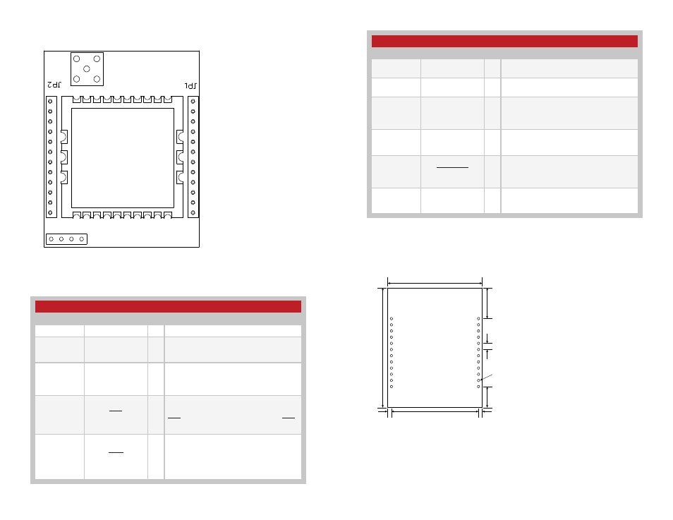
Figure 4: 25 Series EVM Module Pin Assignments (Top View)
Figure 5: 25 Series EVM Module Pin Descriptions
Pin Descriptions
Pin Number
Name
I/O Description
1
VCC
—
Supply Voltage
2
RXD
I
UART Receive Data Input. This is the input
line for the configuration commands as well
as data to be sent over the air.
3
TXD
O
UART Transmit Data Output. This is the
output line for the configuration command
responses as well as the data received over
the air.
4
CTS
O
UART Clear To Send, active low. This line
indicates to the host microcontroller when
the module is ready to accept data. When
CTS is high, the module is busy. When CTS
is low, the module is ready for data.
5
CMD
I
Command Input. This line sets the serial
data as either command data to configure
the module or packet data to be sent over
the air. Pull low for command data; pull high
for packet data.
Pin Descriptions Continued
Pin Number
Name
I/O Description
6, 7, 8, 9, 10,
15, 16, 17, 18
NC
—
No Electrical Connection. Do not connect
any traces to these lines.
11, 12, 13,
14, 23, 24
GND
—
Ground
19
EX
O
Exception Output. A mask can be set
to take this line high when an exception
occurs. The line is lowered when the
exception register is read (regEXCEPTION)
20
RSSI
O
This line outputs an analog voltage that is
proportional to the strength of the incoming
signal.
21
CMD_RSP
O
Command Response. This line is low when
the data on the TXD line is a response to a
command and not data received over the
air.
22
BE
O
Buffer Empty. This line goes high when the
UART input buffer is empty, indicating that
all data has been transmitted.
PCB Footprint
0.10”
(2.54)
Ø0.04” x 24
(1.02)
0.34”
(8.64)
1.40”
(35.56)
0.07”
(1.78)
1.94”
(49.28)
1.53”
(38.86)
1
24
0.06”
(1.52)
0.50”
(12.7)
Figure 6: 250 Series EVM Module PCB Footprint