Ordering information, Electrical specifications, Schematic diagram – Linx Technologies EVM-915-025 User Manual
Page 4
–
–
–
–
2
3
Ordering Information
Ordering Information
Link Part No.
Description
Radiotronix Part No.
EVM-915-025-FCR
TRM-915-R25 Evaluation Module,
915MHz, Right Angle RP-SMA
Connector, FCC Approved
Wi.232FHSS-25-FCC-RA-R
EVM-915-025-FCS
TRM-915-R25 Evaluation Module,
915MHz, Straight RP-SMA Connec-
tor, FCC Approved
Wi.232FHSS-25-FCC-ST-R
Figure 2: Ordering Information
Electrical Specifications
Electrical Specifications
Parameter
Designation
Min.
Typ.
Max.
Units Notes
Power Supply
Operating Voltage
V
CC
4
12
VDC
Supply Current
I
CC
Receive
25
mA
Transmit, Po = -2dBm
35
mA
Transmit, Po = 13dBm
70
mA
Digital Interface
Output
Logic Low
V
OL
0
0.4
VDC
Logic High
V
OH
2.5
V
CC
VDC
Input
Logic Low
V
IL
0
0.3*V
CC
VDC
Logic High
V
IH
0.7*V
CC
V
CC
VDC
Environmental
Operating Temperature Range
–40
85
°C
Figure 3: Electrical Specifications
Note:
Please see the TRM-915-R25 data guide for complete information
about the module, detailed specifications and configuration commands.
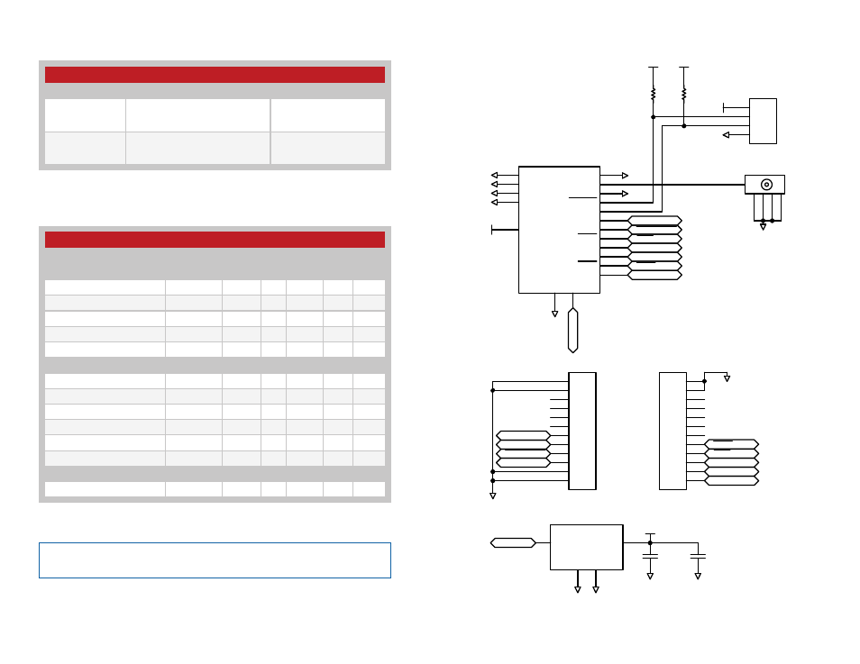
Schematic Diagram
3
+
3
4
5
6
7
8
9
10
11
12
13
14
1
2
3
4
5
6
7
8
9
10
11
12
JP2
GND
J1
GND
3.3V
IN
1
GND
2
GND
T
OUT
U1
GNDGND
VCC
C1
GND
C2
GND
VIN
VIN
GND
1
EX
2
GND
15
GND
16
GND
17
GND
18
VCC
19
MOD1
CTS
CMD
TXD
RXD
GND
1
2
3
4
JP3
1K
R2
1K
R1
VCC
VCC
RESET
BE
CMD
RXD
TXD
CTS
CMD_RSP
RSSI
C2D
GND
ANT
GND
GND
GND
GND
GND
GND
VCC
GND
GND
VCC
TXD
RXD
CMD
CTS
1
2
3
4
5
6
7
8
9
10
11
12
JP1
EX
RSSI
BE
GND
EX
CMD_RSP
RSSI
BE
CMD_RSP
Figure 4: 25 Series EVM Module Schematic