Ordering information, Electrical specifications, Pin assignments – Linx Technologies EVM-915-DTS User Manual
Page 4: Pin descriptions
–
–
–
–
3
2
Electrical Specifications
Electrical Specifications
Parameter
Designation
Min.
Typ.
Max.
Units Notes
Power Supply
Operating Voltage
V
CC
4
12
VDC
Supply Current
I
CC
Receive
25
mA
Transmit, Po = 0dBm
35
mA
Transmit, Po = 13dBm
60
mA
Digital Interface
Output
Logic Low
V
OL
0
0.4
VDC
Logic High
V
OH
2.5
V
CC
VDC
Input
Logic Low
V
IL
0
0.3*V
CC
VDC
Logic High
V
IH
0.7*V
CC
V
CC
VDC
Environmental
Operating Temperature Range
–40
85
°C
Ordering Information
Product Part No.
Description
Radiotronix Part No.
EVM-915-DTS-FCS
TRM-915-DTS Evaluation Module,
915MHz, Straight RP-SMA Connector,
FCC Approved
Wi.232DTS-FCC-ST-R
EVM-915-DTS-FCR
TRM-915-DTS Evaluation Module,
915MHz, Right Angle RP-SMA
Connector, FCC Approved
Wi.232DTS-FCC-RA-R
EVM-915-DTS-BRZ
TRM-915-DTS Evaluation Module,
915MHz, Right Angle RP-SMA
Connector, Brazil Anatel Approved
Wi.232DTSB-EVM-RA-R
EVM-915-DTS-BZS
TRM-915-DTS-BRZ Evaluation
Module, 915MHz, Straight RP-SMA
Connector, Brazil Anatel Approved
Wi.232DTSB-EVM-ST-R
Ordering Information
Figure 2: Ordering Information
Figure 3: Electrical Specifications
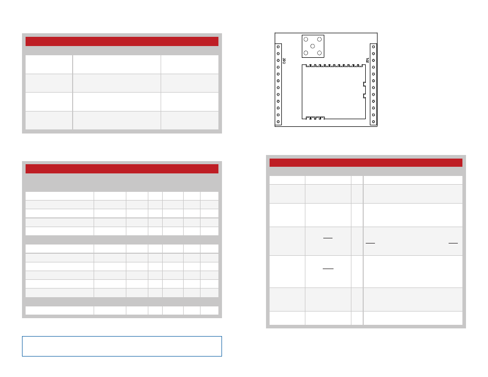
Pin Descriptions
1
2
3
4
5
6
7
8
9
10
11
12
24
23
22
21
20
19
18
17
16
15
14
13
Pin Assignments
Pin Descriptions
Pin Number
Name
I/O Description
1
VCC
—
Supply Voltage
2
RXD
I
UART Receive Data Input. This is the input
line for the configuration commands as well
as data to be sent over the air.
3
TXD
O
UART Transmit Data Output. This is the
output line for the configuration command
responses as well as the data received over
the air.
4
CTS
O
UART Clear To Send, active low. This line
indicates to the host microcontroller when
the module is ready to accept data. When
CTS is high, the module is busy. When CTS
is low, the module is ready for data.
5
CMD
I
Command Input. This line sets the serial
data as either command data to configure
the module or packet data to be sent over
the air. Pull low for command data; pull high
for packet data.
6, 7, 8, 9, 10,
15, 16, 17,
18, 19, 20,
21, 22
NC
—
No Electrical Connection. Do not connect
any traces to these lines.
11, 12, 13,
14, 23, 24
GND
—
Ground
Figure 4: DTS Series EVM Module Pin Assignments (Top View)
Figure 5: DTS Series EVM Module Pin Descriptions
Note:
Please see the TRM-915-DTS data guide for complete information
about the module, detailed specifications and configuration commands.