Master development system – Linx Technologies RXM-GPS-SG User Manual
Page 14
Page 26
Page 27
MASTER DEVELOPMENT SYSTEM
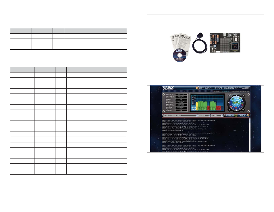
The SG Series Master Development System provides all of the tools necessary
to evaluate the SG Series GPS receiver module. The system includes a fully
assembled development board, an active antenna, development software, and
full documentation.
The development board includes a power supply, a prototyping area for custom
circuit development, and an OLED display that shows the GPS data without the
need for a computer. A USB interface is also included for use with a PC running
custom software or the included development software.
The Master Development System software enables configuration of the receiver
and displays the satellite data output by the receiver. The software can select
from among all of the supported NMEA protocols for display of the data.
Full documentation for the board and software is included in the development
system, making integration of the module straightforward.
Figure 6: The SG Series Master Development System
Figure 7: The SG Series Master Development System Software
215 – Query
The table below contains the values for the following example to read the
configuration and state of all of the GPIO lines:
$PLSC,215*16
The receiver outputs a response to this command. The table below contains the
response for the above command:
For some further examples of this command:
n Set GPIO 1 to low
Input command: $PLSC,215*16
Output response: $PLSR,215,5,1,0,0,10,0,1,13,0,1,14,0,1,15,0,1*00
Name
Example
Units
Description
MID
$PLSC,215
Message ID
Checksum
*16
<CR> <LF>
End of message termination
Table 32: Query Example
Name
Example
Units
Description
MID
$PLSR,215
Message ID
Count
5
Total number of GPIOs
GPIO Number
1
GPIO Number
Configuration
0
Direction; 0 = Input; 1 = Output
Current State
0
0 = Low; 1 = High
GPIO Number
10
GPIO Number
Configuration
0
Direction; 0 = Input; 1 = Output
Current State
1
0 = Low; 1 = High
GPIO Number
13
GPIO Number
Configuration
0
Direction; 0 = Input; 1 = Output
Current State
1
0 = Low; 1 = High
GPIO Number
14
GPIO Number
Configuration
0
Direction; 0 = Input; 1 = Output
Current State
1
0 = Low; 1 = High
GPIO Number
15
GPIO Number
Configuration
0
Direction; 0 = Input; 1 = Output
Current State
1
0 = Low; 1 = High
Checksum
*00
<CR> <LF>
End of message termination
Table 33: Query Response Example