Pin assignments – Linx Technologies LICAL-DEC-MS001 User Manual
Page 5
–
–
–
–
4
5
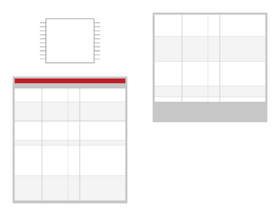
Pin Assignments
Figure 6: MS Series Deccoder Pin Assignments
Pin Descriptions
Pin Number
Name
I/O
Description
1, 2, 13, 14, 17–20
DO–D7
O
Data Output Lines. These
lines reproduce the state of
the encoder's data lines upon
reception of a valid packet.
3
SEL_BAUD0
I
Baud Rate Selection Line 0. This
line along with SEL_BAUD1 sets
the baud rate of the serial data
stream to one of 4 possible rates.
The rate must be set before power
on.
4
SEL_BAUD1
I
Baud Rate Selection Line 1. This
line along with SEL_BAUD0 sets
the baud rate of the serial data
stream to one of 4 possible rates.
The rate must be set before power
on.
5, 6
GND
Ground
7
LATCH
I
Set Latched Outputs. If this line
is low, then the data outputs are
momentary (active for as long
as a valid signal is received). If
this line is high, the outputs are
latched (when a signal is received
to make a particular data line
high, it remains high until another
transmission is received instructing
it to go low).
8
RX_CNTL
I/O
External Receiver Control
Line. This line can be used to
automatically power on and off
a receiver. It powers the receiver
down for ten times as long as
it is powered on. The times are
determined by the selected baud
rate.
Figure 7: Pin Descriptions
D6
D7
SEL_BAUD0
SEL_BAUD1
GND
GND
LATCH
RX_CNTL
TX_ID
MODE_IND
D5
D4
D3
D2
VCC
VCC
D1
D0
DATA_IN
LEARN
1
2
3
4
5
6
7
8
9
10
11
12
13
14
15
16
17
18
19
20
LICAL-DEC-MS001
9
TX_ID
O
Transmitter ID Output Line.
A unique ID number for each
transmitter is stored in the
decoder’s memory. A byte is
output as serial data on this line
to indicate which transmitter a
transmission came from.
10
MODE_IND
O
Mode Indicator Output. This line
switches when a valid transmission
is received, when Learn Mode is
entered, and when the memory
is cleared. This allows for the
connection of a LED to indicate
to the user that these events have
taken place.
11
LEARN
I
Learn Mode Activation Line. When
this line goes high, the decoder
enters Learn Mode to accept an
Address from an encoder and
store it in memory. If it is held high
for ten seconds, the decoder
clears all stored Addresses from
memory.
12
DATA_IN
I
Data Input Line. This line accepts
the encoded serial data stream
from a receiver.
15, 16
V
CC
Supply Voltage
None of the input lines have internal pull-up or pull-down resistors. The input lines must
always be in a known state (either GND or V
CC
) at all times or the operation may not
be predictable. The designer must ensure that the input lines are never floating, either
by using external resistors, by tying the lines directly to GND or V
CC
, or by use of other
circuits to control the line state.