Theory of operation, Using the kit, Setting the address – Linx Technologies OEM Transmitter Evaluation Kit User Manual
Page 5
–
–
–
–
4
5
Theory of Operation
OEM Transmitters
Linx OEM transmitters are a great way to quickly bring a remote control
product to market. They are fully assembled and certified, eliminating the
need for design, tooling, and certification. Linx can also customize the
transmitters with customer specific art, logos or switch layouts.
The operation of the OEM transmitter is straightforward. When a button(s)
is pressed on the OEM transmitter, the states of D0 to D7 are formatted
into packets by an on-board encoder IC. These encoded packets are sent
to a Linx transmitter that, through the antenna, conveys the data into free
space.
Receiver / Decoder Evaluation Board
The receiver board is powered by two AAA batteries. A Linx LR Series
receiver is used for reception of the transmitted signal. This receiver
provides exceptional sensitivity, allowing the transmitter and receiver to
operate at distances of up to 1,000 feet (depending on TX model and
signal conditions). The data recovered by the receiver is decoded by the
DS Series set as a decoder. If the settings of the 10-position DIP switch on
the receiver board match the address setting of the transmitter, the data
line outputs are updated to match the state of the buttons on the OEM
transmitter. To demonstrate this, one data line on the evaluation board is
used to drive a buzzer while the other lines activate LEDs. This board also
has a prototyping area with all of the receiver and decoder lines brought
out to a header.
Using the Kit
Using the kit is straightforward. Simply attach the antenna to the board and
install the batteries. Set the address on the transmitter and on the board
to the same settings, turn on the power to the board, and press a button
on the transmitter. When D0 is pressed, the buzzer sounds; when S1–S7
are pressed, the LEDs turn on. When any button (D0–D7) is pressed on the
transmitter, the corresponding decoder output (D0–D7) is active high (V
CC
)
on the prototyping header.
Setting the Address
The DS Series encoder and decoder each have ten address lines that must
match in order for the transmitter and receiver to talk to each other. If they
do not match, then the decoder ignores the transmission and takes no
action.
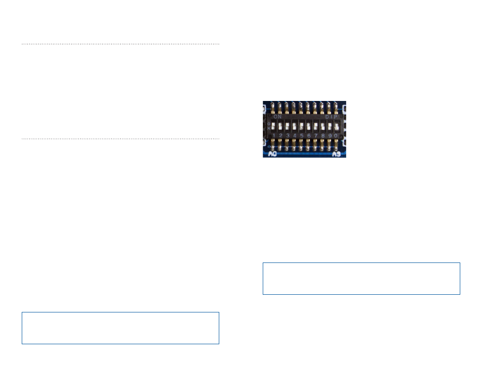
To set the address on the receiver evaluation board, note the A0–A9 labels
on the board and turn the DIP switches on or off as desired. If a switch is
on, the address line is connected to ground. If it is off, then the address line
is pulled high to VCC.
The four OEM transmitters have different ways of setting their address
lines. For your convenience, a brief explanation follows; however, the OEM
transmitter manual or Application Note AN-00300 should be referenced for
complete details.
The HHCP and HHLR utilize a ten-position DIP switch that is accessed by
a cover on the back of the remote. The switch numbers match the address
lines with switch number 1 corresponding to A0 and number 10 to A9.
The Keyfob has ten internal cut traces numbered 0 to 9 to match A0 to A9.
If the trace is intact, it is connected to ground; when cut, it is floating.
Note:
All switches (address, protocol select and interpretation
configuration) must match on both the transmitter and the decoder /
receiver board.
Figure 4: The Evaluation Board Address DIP Switch
Note:
All address switches ON and all switches OFF are not valid
states and are not recognized by the decoder. At least one switch
must be set differently from the rest.