Linx Technologies FCTN-WALL-xxx User Manual
Page 3
FUSE REPLACEMENT
An internal fuse protects the AC Function
Module if the output is shorted or an
excessive load is attached. Following such an
event, the fuse can be replaced by unplugging
the unit, removing the 4 rear screws, folding
the cover over (DO NOT UNPLUG THE
WIRES GOING TO THE COVER
RECEPTACLE), and unclipping the fuse. The
location of the fuse is shown in Figure 4.
Replace only with an approved type and
rating of fuse (See UL Compliance section).
Never use a different value or attempt to
bypass the fuse, as extensive damage to the
module, equipment, or property may result. If
the fuse blows immediately after replacement,
service may be required.
ANTENNA ORIENTATION
It is always important to remember that the control signals for the AC Function
Module are sent through the air. For this reason, the physical orientation of the
transmitter and receiver plays an important role in determining the overall range.
The antenna may be swiveled to adjust for maximum range in your environment.
In most cases, orienting the antenna in a vertical position will result in optimum
performance.
CONTENTION CONSIDERATIONS
When working in a wireless environment it is always important to distinguish
between uniqueness and contention. The address lines provided on OEM
modules allow for the uniqueness of system components, however, this does not
eliminate contention between transmitted signals in free space. For this reason
only one transmitter at a time can be active on the same frequency within a
reception area without creating interference. If two or more transmitters are
activated at the same time, the AC Function Module will receive a corrupted
signal and take no action. An unlimited number of AC Function Modules may be
successfully operated in proximity without interference since they contain a
receiver rather than a transmitter.
Page 5
Page 4
Wall Mount
Power Strip
Figure 5: FCTN-WALL-*** Antenna Orientation
INTERFERENCE CONSIDERATIONS
The range performance of the modules is heavily dependent on the environment
in which they are operated. The effects of interference, multipath, and physical
attenuation will vary significantly from location to location.
The AC Function Module is based on the Linx LR Series RF receiver. It utilizes
OOK AM-based modulation. AM devices can be affected by external noise, such
as that from motors or other sources of broadband RF emissions. Interference
can also come from sources such as paging towers or amateur radio activity.
The designer should carefully test the AC Function Module in the environment in
which it will be used to ensure that its performance is appropriate for the chosen
application.
TRANSMITTER CONSIDERATIONS
The AC Function Module incorporates a Linx LR Series receiver. There are
several options available for controlling the module.
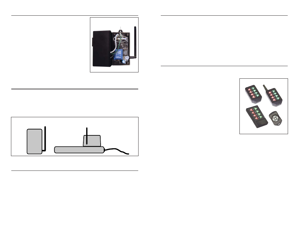
The first option is to use one of the pre-
certified OEM transmitters offered by Linx.
These transmitters come in several packages
and can be customized to bear the logo or
other artwork required by the customer. The
only setup required by the customer is to set
the address of the transmitter and the AC
Function Module.
There are four OEM transmitters that can be
used with the AC Function Module: the Full-
Size Handheld, the Compact Handheld, the
Long-Range Handheld, and the Keyfob. The
Full-Size Handheld uses eight address lines
while the AC Function Module uses four. This
means that the last four address lines (A4
through A7) on the Full-Size Handheld should
be turned off.
The other three transmitters use all ten address lines offered by the Holtek ICs,
while the AC Function Module uses four. This means that the last six address
lines (A4 through A9) on the transmitters must be left floating (turn off the DIP
switches on the handhelds, cut traces 4 through 9 on the Keyfob). The other
address lines can be set to whatever the user desires, as long as the transmitter
and the AC Function Module match.
A custom transmitter can also be created with a KH2 Series transmitter or an LC
or LR Series transmitter paired with a Holtek encoder or microprocessor.
Because these devices offer all ten address lines used by the Holtek ICs, the last
six lines (A4 through A9) must be left open. The Holtek address lines are tri-
state, meaning that they have three valid input conditions: high, low, or floating.
The AC Function Module uses only the low and floating states, so the custom
transmitter can only use these states as well. The lines that are floating should
be left open and have no electrical connection.
Figure 6: Pre-Certified Transmitters
Fuse
Figure 4: FCTN-WALL-418 Fuse