Start up, Shutdown, Maintenance – LowFlow JB Series Back Pressure Regulators User Manual
Page 2
Start Up
Caution! Do not exceed the maximum rated pressure of
the regulator if installed for a hydrostatic test. Isolate the
unit if the test is above the valve rating.
1. Start with the block valves closed. A bypass valve
should be used to maintain upstream pressure in the
system without changing the following steps.
2. Relax the range spring (8) by turning the adjusting
knob (10) counter-clockwise (CCW) until there is no
noticeable spring tension.
3. Slowly open the inlet block valve. Note: if no bypass
valve is installed, extra caution should be used in
starting up a cold system; i.e. do everything slowly.
4. Slowly open the outlet (downstream) block valve.
5. Slowly rotate the regulator adjusting knob (10) clock-
wise (CW) until flow begins.
6. Develop system flow to a level near its expected
normal rate, and reset the regulator set point by
turning the adjusting knob (14) CW to increase inlet
pressure, or CCW to reduce inlet pressure.
7. Reduce system flow to a minimum level and observe
set point. Inlet pressure will rise from the set point of
Step 6.
Shutdown
1. On systems with a bypass valve, and where system
pressure is to be maintained as the regulator is shut-
down, slowly open the bypass valve while closing
the inlet (upstream) block valve. (When on bypass,
the system pressure must be constantly observed
and manually regulated.) CAUTION! Do not walk
away and leave a bypassed regulator unattended.
2. If the regulator and system are to both be shut
down, slowly close the inlet (upstream) block valve.
Close the outlet (downstream) valve only if regulator
removal is required.
Maintenance
Warning! System Under Pressure.
Prior to performing
any maintenance, isolate the regulator from the system
and relieve all pressure. Failure to do so could result in
personal injury.
A. General
1. Maintenance procedures can be done after re-
moval of the regulator unit from the pipeline where
installed, it may be maintained in-line if it is safe to
do so.
2. 2. Always follows local or company procedures
for removal, handling, cleaning and disposal of
non-reuseable parts, i.e. gaskets, etc.
B. Trim Replacement
Note: One of the features designed into the JR valves is
that a complete trim replacement and wet side cleaning
can be done with the valve still installed, without com-
plete disassembly. Make sure all upstream and down-
stream valves are closed and all pressure is relieved
prior to beginning work.
1. Remove adjusting screw assembly (10) completely
out of the spring housing (7).
2. If valve is removed from the line, clamp the valve in
a vise using the body (1).
3. Remove spring housing (7).
4. Remove range spring (8) and spring seat (9).
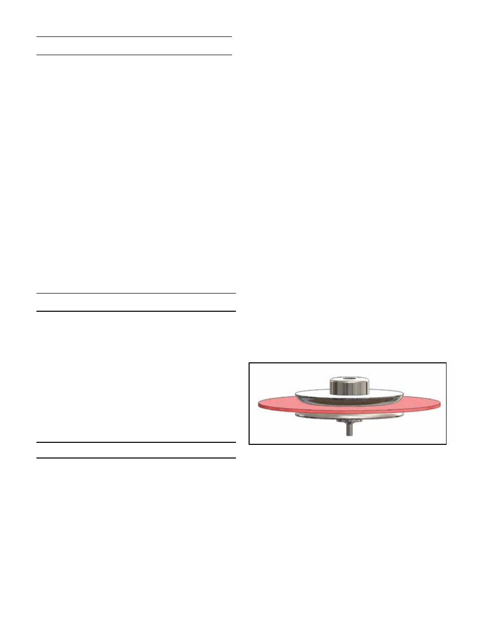
5. Remove diaphragm assembly parts (4), (5), and
(6). See Figure 1.
6. Inspect all parts for damage and replace if neces-
sary. Note: Use only parts manufactured and sup-
plied by LowFlow Valve for these parts.
7. Remove seat assembly (2) from body (1).
8. Place seat assembly (2) into body (1).
9. Refer to Figure 1. Unscrew the lower diaphragm
plate (4) from the upper diaphragm plate (6). Dis-
card the old diaphragm (5) and reassemble with
new one. Use LowFlow replacement diaphragm
only.
10. Place diaphragm assembly parts (2), (3), and (4)
back into body cavity (1), making sure the small tip
on the bottom of lower diaphragm plate is properly
engaged with the seat assembly (2).
11. Replace range spring (8), spring seat (9), center-
ing both on top of the upper diaphragm plate (6).
Replace housing (7) and adjusting screw (10).
-2-
Figure 1: Diaphragm Subassembly