Start up, Shutdown, Maintenance – LowFlow JBPH Series Back Pressure Regulating Valve User Manual
Page 2
Start Up
Caution! Do not exceed the maximum rated pressure of the regulator
if installed for a hydrostatic test. Isolate the unit if the test is above the
valve rating.
1.
Start with the block valves closed. A bypass valve should be used
to maintain upstream pressure in the system without changing the
following steps.
2.
Relax the range spring (3) by turning the adjusting knob (6) coun-
ter-clockwise (CCW) until there is no noticeable spring tension.
3.
Slowly open the inlet block valve. Note: if no bypass valve is
installed, extra caution should be used in starting up a cold system;
i.e. do everything slowly.
4.
Slowly open the outlet (downstream) block valve.
5.
Slowly rotate the regulator adjusting knob (6) clockwise (CW) until
fl ow begins.
6.
Develop system fl ow to a level near its expected normal rate, and
reset the regulator set point by turning the adjusting knob (6) CW
to increase inlet pressure, or CCW to reduce inlet pressure.
7.
Reduce system fl ow to a minimum level and observe set point. Inlet
pressure will rise from the set point of Step 6.
Shutdown
1.
On systems with a bypass valve, and where system pressure is
to be maintained as the regulator is shutdown, slowly open the
bypass valve while closing the inlet (upstream) block valve. (When
on bypass, the system pressure must be constantly observed and
manually regulated.) CAUTION! Do not walk away and leave a
bypassed regulator unattended.
2.
If the regulator and system are to both be shut down, slowly close
the inlet (upstream) block valve. Close the outlet (downstream)
valve only if regulator removal is required.
Maintenance
Warning! System Under Pressure. Prior to performing any
maintenance, isolate the regulator from the system and
relieve all pressure. Failure to do so could result in personal
injury.
A. General
1.
Maintenance procedures can be done after removal of the regulator
unit from the pipeline where installed; it may be maintained in-line
if it is determined safe to do so.
2.
Always follow local or company procedures for removal, handling,
cleaning and disposal of non-reuseable parts, i.e. o-rings, etc.
B. Trim
Replacement
1.
Remove adjusting screw assembly (6) completely out of the spring
housing (5).
2.
Clamp the valve in a vise using the body (1).
3.
Remove the SHCS (13) then lift off spring housing (5).
4.
Remove range spring (3) and upper spring guide (4).
5.
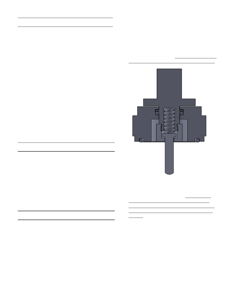
Remove piston assembly ( (7), (16), (17), and (18)). Remove
cylinder face seal (10) and discard. Note: the return spring (19) and
seals (9) and (11) are enclosed inside this assembly. See Figure 2.
6.
Refer to Figure 2. Place the piston assembly into a vise with the
plug (18) pointing upward. Unscrew the plug holder (16) from the
piston (17) using a ¾” deep-welled socket. Caution: The return
spring (19) is captured between the piston (17) and plug/plug
holder (18/16). Take special care while disassembling the parts to
prevent injury from the release of the plug holder (16) and return
spring (19). Discard the old cylinder seals (9)(11) and replace with
new ones (lubricate lightly with Krytox lubricant). Reassemble the
piston assembly. Install new cylinder face seal (10) into bottom of
cylinder (7) (lubricate lightly with Krytox lubricant).
7.
Place the body (1) back in the vise right side up. Place piston as-
sembly back in body (1), taking special care to guide the plug (18)
into the bore hole in the body (1).
8.
Place range spring (3) on top of piston assembly. Place upper
spring guide (4) on top of spring (18).
9.
Place spring housing (5) on top of body (1). Thread SHCS (13) into
body hand tight. Cross tighten to 200 in lbs.
10. Thread adjusting knob (6) into spring housing (5)
11. Invert the body and remove the bottom cap (2) from body (1).
-2-
Figure 2