Troubleshooting, Trim, Torque procedures – LowFlow Mark 6800HP Series High Pressure Regulating Valve User Manual
Page 3
-3-
Troubleshooting
Symptom
Possible Cause and Cure
• Erratic Control
1. Oversizing causes cycling and hunting and reduces
the rageability of the valve. Make certain that your
sizing is correct.
2. Safety valve may be jammed open. Repair as
necessary.
3. Excessive foreign matter on seat (10) or orifice
(11). Clean them. Inspect seating surfaces for
deterioration.
4. Valve trim may not be moving freely. Check for any
parts that may be binding.
• Downstream Pressure Build-Up
1. Seats deteriorated. Replace.
2. Inspect for foreign matter between the seat (10) and
orifice (11).
3. Metal hard seat not supplying tight enough shutoff.
Consider using soft seat.
4. O-ring (9, 14 or 15) not sealing. Replace.
• Cannot Maintain Regulated Pressure
1. Inlet pressure too low.
2. Clogged strainer or lines. Clean.
3. Spring (25) set too low or broken. Reset or replace.
4. Valve is undersized for rated flow. Recheck sizing.
5. System demand exceeds capacity. Recheck sizing.
Troubleshooting
Low Flow Valves are ruggedly built, carefully assembled
to accurate dimensions, and individually tested for per-
formance. A complete stock of finished parts is main-
tained ready for immediate shipment.
If desired, Low Flow Valve will promptly repair your
regulator at a reasonable cost. To return a valve for
inspection and/or repair, please contact our customer
service department for a Return Authorization Number.
Phone toll-free at 1-800-543-7311. If preferred, you may
fax us at 513-871-0105.
When ordering spare parts, first make a note of the fol-
lowing information on the valve's nameplate:
• serial number
• model number and size
• body material and end connections
• range
• seat and seal materials
Trim
1. Lubricate and place the o-ring (5) and two back-up
rings (4) into the groove on the bottom cap (1) be-
ing careful not to cut the o-ring on the threads.
2. Place the return spring (3) into the bottom cap (1).
3. Lubricate and insert the o-ring (9) into the seat
retainer (8).
4. Insert the seat (10) into the seat retainer (8).
5. Install the stem (12) through the seat (10) and seat
retainer (8). Secure in place with retaining ring (7).
6. Lubricate and place the o-ring (14) into the groove
on the guide (2) being careful not to cut the o-ring
on the threads. If the valve has balanced trim, lu-
bricate and place the o-ring (35) and two back-up
rings (36) into the groove on the guide (2).
7. Apply Loctite No. 242 onto the threads of the guide
(2) and thread into the seat retainer (8). Tighten
the seat retainer until it is seated firmly against the
guide.
8. Place the completed trim subassembly into the
bottom cap (1). The stem (12) should be facing
out.
9. Apply Loctite No. 242 onto the threads of the bot-
tom cap (1) and thread into the body (6). The stem
(12) should locate into the hole in the bottom of
the piston (19). Tighten the bottom cap until it is
seated firmly against the stop in the body.
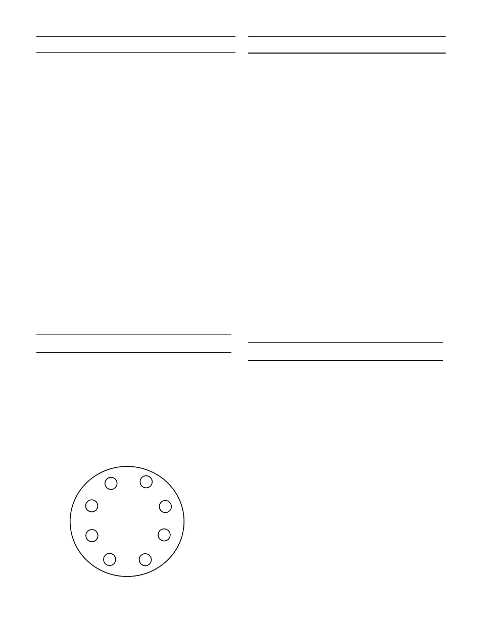
Torque Procedures
1. Install all bolts hand-tight.
2. Torque the bolts in order of the bolt pattern to a
value equal to 1/4 of the recommended torque
value.
3. Restore each bolt to 32 ft-lbs using the same bolt
pattern as shown.
Bolt Pattern/Torque Sequence
(8 bolts or multiples)
+
2
6
4
8
1
5
3
7