Shutdown, Maintenance – LowFlow JR Series High Pressure Regulators User Manual
Page 2
3.
If it is a “hot” piping system, and equipped with a
bypass valve, slowly open the bypass valve to pre-
heat the system piping and to allow slow expansion
of the piping. Closely monitor outlet (downstream)
pressure via gauge to ensure no over-pressurizing.
Note: if no bypass valve is installed, extra caution
should be used in starting up a cold system; i.e. do
everything slowly.
4.
Crack open the outlet (downstream) block valve.
5.
Slowly open the inlet (upstream) block valve ob-
serving the outlet (downstream) pressure gauge.
Determine if the regulator is flowing. If not, slowly
rotate the regulator adjusting knob (12) clockwise
(CW) until flow begins.
6.
Continue to slowly open the inlet (upstream) block
valve until fully open.
7.
Continue to slowly open the outlet (downstream)
block valve, especially when the downstream piping
isn’t pressurized. If the outlet (downstream) pres-
sure exceeds the desired pressure, close the block
valve and go to Step 2, then return to Step 4.
8.
When flow is established steady enough that the
outlet (downstream) block is fully open, begin to
slowly close the bypass valve if installed.
9.
Develop system flow to a level near its expected
normal rate, and reset the regulator set point by
turning the adjusting knob (12) CW to increase out-
let pressure, or CCW to reduce outlet pressure.
10. Reduce system flow to a minimum level and ob-
serve set point. Outlet pressure will rise from the
set point of Step 9.
Shutdown
1.
On systems with a bypass valve, and where sys-
tem pressure is to be maintained as the regulator
is shutdown, slowly open the bypass valve while
closing the inlet (upstream) block valve. (When on
bypass, the system pressure must be constantly
observed and manually regulated.) Close the outlet
(downstream) block valve. CAUTION! Do not walk
away and leave a bypassed regulator unattend-
ed.
2.
If the regulator and system are to both be shut
down, slowly close the inlet (upstream) block valve.
Close the outlet (downstream) valve only if regulator
removal is required.
Maintenance
Warning! System Under Pressure. Prior to perform-
ing any maintenance, isolate the regulator from the
system and relieve all pressure. Failure to do so could
result in personal injury.
A. General
1.
Maintenance procedures hereinafter are based
upon removal of the regulator unit from the pipe-
line where installed.
2.
Owner should refer to owner’s procedures for
removal, handling, cleaning and disposal of non-
reuseable parts, i.e. gaskets, etc.
B.
Trim Replacement
Note: One of the features designed into the JR valves is
that a complete trim replacement and wet side cleaning
can be done with the valve still installed, without complete
disassembly. But please note the caution above. Make
sure all upstream and downstream valves are closed and
all pressure is relieved prior to beginning work.
1.
Remove adjusting screw assembly (12) completely
out of the spring housing (11).
2.
If valve is removed from the line, clamp the valve in
a vise using the body (1).
3.
Remove spring housing (11).
4.
Remove range spring (5) and spring seat (13).
5.
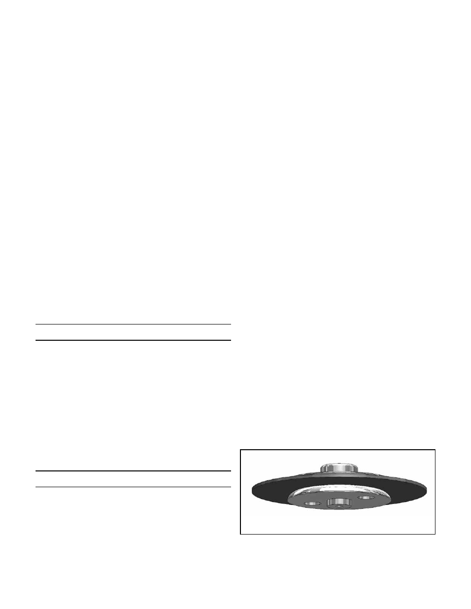
Remove diaphragm assembly parts (2), (3), and (4).
See Figure 1.
6.
Inspect all parts for damage and replace if neces-
sary. Note: Use only parts manufactured and sup-
plied by LowFlow Valve for these parts.
7.
Remove seat holder (9), seat (10) and plug (8) from
body (1).
8.
Place new plug (8) into body chamber. Make sure
the bottom stop rod (bigger end) of the plug (8)
goes down inside the return spring (6).
9.
Place the new seat (10) into the seat holder (9) and
carefully install into body cavity (1) taking care not
to bend the narrow rod on top of the plug (8) when
it passes through the seat holder (9).
10. Refer to Figure 1. Unscrew the lower diaphragm
plate (4) from the upper diaphragm plate (2). Dis-
card the old diaphragm (3) and reassemble with
new one. Use LowFlow replacement diaphragm
only. Place diaphragm assembly parts (2), (3), and
(4) back into body cavity (1), making sure the small
counterbore on the bottom of lower diaphragm
plate is properly engaged with the narrow tip of the
plug (8) which protrudes through the seat holder
(9).
11. Replace range spring (5), spring seat (13), centering
both on top of the upper diaphragm plate (4). Re-
place housing (11) and adjusting screw (12). Even if
-2-
Figure 1: Diaphragm Subassembly