Kcl97-300262-p7, Finishing the installation – Kichler 300262 User Manual
Page 8
7
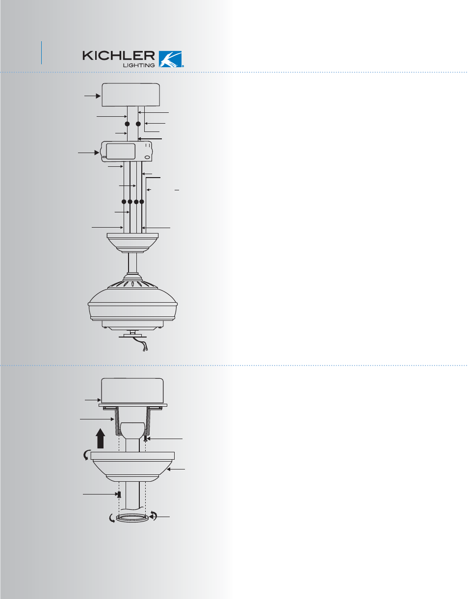
Fig. 14
Fig. 15
White (neutral)
Green or bare
copper (ground)
White ("AC IN N")
Outlet box
Black (hot)
Black ("AC IN L")
Receiver
White (neutral)
White ("to motor N")
Ground
(green)
(Connect to
ground wire on
hanger bracket
if no house
ground wire
exists.)
Black ("to motor L")
Blue (for bottom light)
Orange (for upper light)
Black (motor)
Step 1. Tuck all the connections neatly into the
ceiling outlet box.
Step 2. Slide the canopy up to the mounting
bracket and place one of the key hole slots over
the mounting screw on the mounting bracket.
Rotate the canopy until the screw head locks in
place at the narrow section of the key hole. See
figure 15.
Step 3. Align the remaining circular hole on the
canopy with the remaining hole on the Ceiling
Mounting Bracket. Insert and tighten the
mounting screw you removed earlier and the
mounting screw from Step 2 above. Now, attach
the canopy cover to the mounting screw heads
by inserting the screw heads into the bottom
side of the canopy cover and rotating the cover
clockwise.
NOTE: Adjust the canopy screws as necessary
until the canopy and canopy cover are snug.
(Fig. 15)
Connect the white wire from the fan to the white
wire marked "TO MOTOR N" from the receiver.
Connect the blue wire from the fan to the blue
wire marked "FOR BOTTOM LIGHT" from the
receiver. Connect the orange wire from the fan
to the orange wire marked "FOR UPPER
LIGHT" from the receiver. Secure all the wire
connections with the plastic wire nuts provided.
Step 3. (Fig. 14) Receiver to House Supply
Wires Electrical Connections: Connect the black
(hot) wire from the ceiling to the black wire
marked "AC in L" from the receiver. Connect the
white(neutral) wire from the ceiling to the white
wire marked "AC in N" from the Receiver.
Secure the wire connections with the plastic wire
nuts provided.
Step 4. (Fig. 14) If your outlet box has a ground
wire (green or bare copper) connect it to the fan
ground wires; otherwise connect the hanging
bracket ground wire to the mounting bracket.
Secure the wire connection with a plastic nut
provided. After connecting the wires, spread
them apart so that the green and white wires are
on one side of the outlet box and black, orange
and blue wires are on the other side. Carefully
tuck the wire connections up into the outlet box.
Note: Fan must be installed at a maximum
distance of 30 feet from the CoolTouch™
Remote Transmitter for optimal signal
transmission between the transmitter and the
fan's receiving unit.
8. FINISHING THE INSTALLATION
Outlet box
Ceiling
mounting
bracket
Canopy
Canopy cover
Screws
Screws