Installation, Specifications 4. operation – Sealey LP200 User Manual
Page 2
3. INSTALLATION
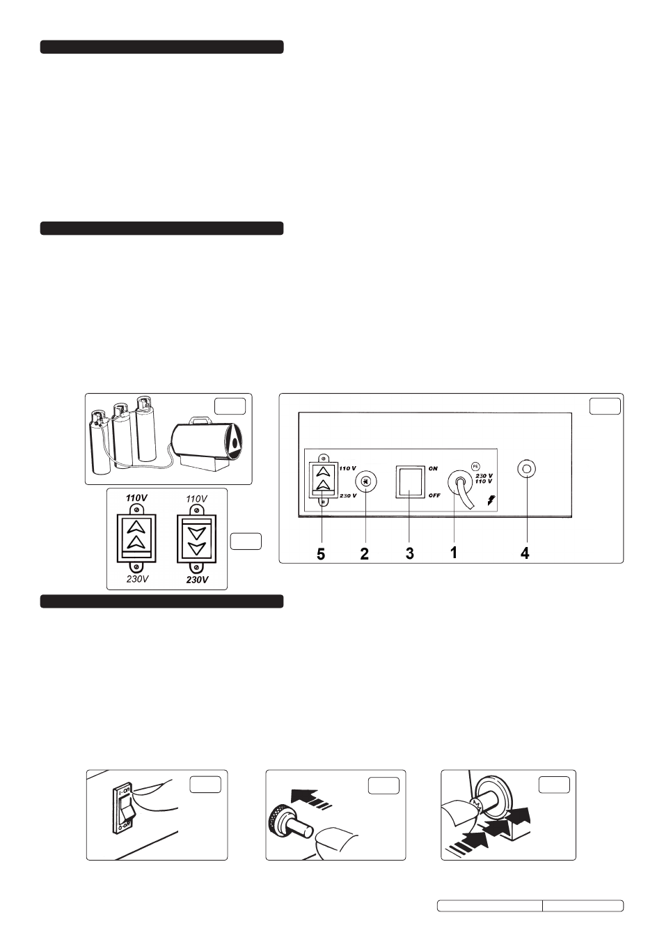
Note: If a small gas cylinder is used, the heater may not operate at maximum efficiency. It is recommended to use two or more cylinders
linked in parallel, to achieve maximum continuous efficiency (fig.1).
3.1.
Setting heater supply voltage.
3.1.1. locate the voltage selection switch (fig.2.5).
3.1.2. If the correct supply voltage is not selected, remove the cover, select the required voltage position and refit the cover panel (fig.3).
3.2.
Connections
3.2.1. Check heater and gas cylinder to ensure that they are both in good condition. If not, stop and contact your supplier immediately.
3.2.2. Site the heater and gas cylinder in the location to be heated.
3.2.3. Connect the heater to an electrical supply outlet, ensuring that the machine is correctly earthed. See safety instructions.
3.2.4. Connect the gas supply hose to the excess flow valve, connect the valve to the pressure regulator, and connect the regulator to the
gas cylinder. note: left hand threads. Connect the other end of the supply hose to the heater. Ensure all connections are tight.
3.2.5. Gradually open the tap of the gas cylinder. Check hose and all fittings for gas leaks.
WARNING! DO NOT USE A NAKED FLAME! To check for leaks, we recommend the use of a foamy soap solution.
2. SPECIFICATIONS
4. OPERATION
IMPORTANT: To ensure continuous ventilation to the heater area, a ventilation opening must connect to the outside of the premises where the heater is to
operate. The opening must be 100cm
2
for every kW, and must be set at an equal distance from the upper and lower parts of heater operating area.
4.1.
Switching Heater On
4.1.1. Turn the on/off switch to the 'on' position (fig.4) and check that the fan starts running.
4.1.2. Push the gas valve button in and hold (fig.5), then press repeatedly on the Piezo Ignition Button (fig.6) until the flame ignites.
4.1.3. When the flame has ignited and the heater has started, keep the gas valve button pushed in for a further 10 seconds before releasing it.
4.1.4. If the heater stops when the gas valve button is released, leave the fan on, but wait for one minute before repeating the ignition
sequence. Hold the gas valve button in for 15 seconds this time, before releasing.
4.1.5. The heat output is controlled by adjusting the gas pressure via the regulator. Turn the regulator knob anti-clockwise to reduce the
gas pressure / heat, and clockwise to increase the gas pressure / heat.
4.2.
Switching Heater Off
4.2.1. Shut off the gas cylinder tap. Allow the fan to continue running until the flame shuts down, then turn the on/off switch to the 'oFF'
position. Isolate the heater from the electrical supply.
Model No: . . . . . . . . . . . . . . . . . . . . . LP200.V4. . . . . . . . . . . . . . . LP300.V5 . . . . . . . . . . . . . . . . . . . LP400
Output:. . . . . . . . . . . . . . . . . . . . . . . . . 23-55kW. . . . . . . . . . . . . . . . 33-80kW . . . . . . . . . . . . . . . . 35-109kW
Output:. . . . . . . . . . . . . . .78,500-187,800Btu/hr. . . . . 112,700-273,150Btu/hr . . . . . . 119,500-372,200Btu/hr
Airflow: . . . . . . . . . . . . . . . . . . . . . 1,400mtr
3
/hr. . . . . . . . . . . . . 2,100mtr
3
/hr . . . . . . . . . . . . . . 3,260mtr
3
/hr
Fuel Consumption:. . . . . . . . . . 1.64-3.93kg/hr. . . . . . . . . . . .2.36-5.72kg/hr . . . . . . . . . . . . .2.53-7.77kg/hr
Electrical Input: . . . . . . . . . . . . . . . . 110/230V. . . . . . . . . . . . . . . .110/230V . . . . . . . . . . . . . . . . .110/230V
Length x Width x Height: 558 x 455 x 546mm. . . . . . . 775 x 455 x 546mm . . . . . . .1,015 x 435 x 610mm
Fuel:. . . . . . . . . . . . . . . . . . . . . . . . . . . Propane. . . . . . . . . . . . . . . . Propane . . . . . . . . . . . . . . . . . Propane
Heated Volume:. . . . . . . . . . . . . . . . . .41,742ft
3
. . . . . . . . . . . . . . . . 60,716ft
3
. . . . . . . . . . . . . . . . . 82,725ft
3
Heated Volume:. . . . . . . . . . . . . . . . . 1,182mtr
3
. . . . . . . . . . . . . . . 1,720mtr
3
. . . . . . . . . . . . . . . . 2,343mtr
3
WARNING! If the flame shuts down during operation, before repeating the ignition sequence, make sure that the fan is not jammed, and the air
inlet and outlet are completely free of obstructions.
If it is due to overheating, the cause of the problem must be determined and corrected before
repeating the ignition procedure.
fig.2
fig.4
fig.5
fig.6
fig.1
fig.3
Propane heaters are fan assisted and fitted with a piezoelectric ignition system for trouble-free starting. Supplied with a propane gas regulator.
These heaters are tested and certified to CE standards by the German DVGW test house, and are safe for use in the UK. All regulators are Calor
approved.
1 - Power Supply Cable
2 - Piezo Ignition Button
3 - on/off Switch
4 - Gas Valve Button
5 - Voltage Selection Switch
lP200.V4, lP300.V5, & lP400 Issue no: 2 - 09/12/11
Original Language Version