Operation, Contents & installation, Fig.1 fig.2 fig.3 fig.4 – Sealey SA306F User Manual
Page 2
4. OPERAtION
4.1.
Digital Pressure gauge
4.1.1. sA306, 306fr and sA306r are fitted with a digital pressure gauge (fig.2). Press the function button
to turn on the display and continue to press the function button to scroll through the units of pressure
measurement. stop pressing the function button when the required unit of measurement is displayed.
4.1.2. to extend battery life, the display will automatically turn off after a period of time. Press the function
button to re-activate the display at any time.
4.1.3. should the battery require replacing, drain the air from the system and unscrew the digital pressure
gauge from the regulator. slide off the battery cover to access the battery (fig.3) and remove the
battery. replace battery, refit the battery cover and screw the digital pressure gauge back on to the
regulator.
4.2.
Regulator
4.2.1. the output pressure is controlled by the knob. Before pressurising the air system for the first time,
push down and rotate the knob anticlockwise to remove any loading on the regulator spring.
4.2.2. Pressurise the system and then rotate knob clockwise to set the required output pressure, as shown
on the gauge. When the required pressure is achieved, pull up the knob to prevent inadvertent
adjustment.
Note: for correct pressure setting always adjust up from a lower pressure. therefore to reset from
90psi to 70psi for example, reduce pressure from 90psi to 60psi and then increase to 70psi.
4.3.
Filter
4.3.1. the bowl should be drained regularly to prevent an excessive build-up of water/oil. Pull down the
drain valve at the bottom of the bowl, allow to drain and then release.
4.4.
Lubricator
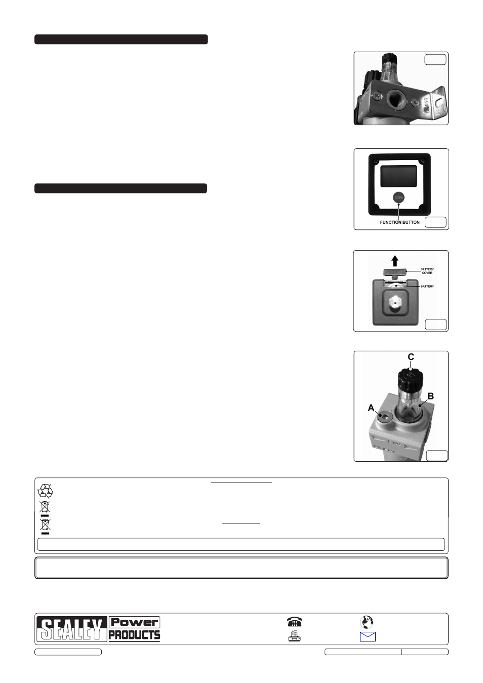
4.4.1. remove the filler plug (fig.4.A) and fill the bowl with air tool oil (sealey Part no. Ato500 or
Ato1000). this can be done with the system pressurised. With air flowing through the lubricator the
oil delivery rate can be adjusted by the screw (fig.4.c) whilst watching the drip rate through the sight
dome (fig.4.B). the oil delivery rate will automatically increase or decrease in line with the air flow.
4.5.
Filter and Lubricator Bowls
4.5.1. Both the filter and the lubricator are supplied with a polycarbonate/metal bowl. to remove, rotate the
bowl anticlockwise until it has released from the main body of the filter or lubricator.
WARNINg! filter and lubricator bowls are manufactured from polycarbonate and must not be used at
temperatures over 140°f (60°c) or for pressures over 170psi (12bar). Polycarbonate can be
damaged and may fail if exposed to certain solvents either internally or externally, such as strong
alkalies, compressor oils containing aromatic hydrocarbons or fire retardant oils, or the fumes of any
of these. clean with warm water only.
3. CONtENtS & INStALLAtION
3.1.
Contents
3.1.1. confirm that all items are present and undamaged. If any parts are missing or damaged please
contact the supplier.
SA306 - combined filter, regulator with gauge, lubricator and mounting brackets.
SA306FR - combined filter, regulator with gauge and mounting brackets.
SA306L - Lubricator.
SA306F - filter
SA306R - regulator with gauge and mounting brackets.
3.2.
Installation
3.2.1. filter/regulator - Attach the mounting brackets to the filter/regulator as shown in fig.1 and install for
connection to the pneumatic system. Before connecting to the pneumatic system ensure that the
gauge is visible, unused gauge port is sealed with plug provided and that the flow direction arrows
match the system flow.
3.2.2. filter and Lubricator - Install into pneumatic system or connect directly to the regulator using fittings
provided. Always check that flow arrows are correct and that the filter is upstream, and the lubricator
is downstream, of the regulator.
Note: to ensure air-tight joints, use PtfE tape on fittings.
NOTE: It is our policy to continually improve products and as such we reserve the right to alter data, specifications and component parts without prior notice.
IMPORtANt: no liability is accepted for incorrect use of this product.
WARRANtY: Guarantee is 12 months from purchase date, proof of which will be required for any claim.
INFORMAtION: for a copy of our latest catalogue and promotions call us on 01284 757525 and leave your full name and address, including postcode.
01284 757500
01284 703534
Sole uK Distributor, Sealey group,
Kempson Way, suffolk Business Park
,
Bury st. Edmunds, suffolk,
IP32 7Ar
www.sealey.co.uk
Web
Original Language Version
sA306/306f/306fr/306L/306r Issue: 1 - 30/07/12
fig.1
fig.2
fig.3
fig.4
Parts support is available for this product. to obtain a parts listing and/or diagram, please log on to www.sealey.co.uk,
email [email protected] or phone 01284 757500.
Environmental Protection.
recycle unwanted materials instead of disposing of them as waste. All tools, accessories and packaging should be sorted, taken to a recycle centre and disposed of in a manner
which is compatible with the environment.
When the product is no longer required, it must be disposed of in an environmentally protective way.
Battery Removal
remove as described in 4.1.3. Dispose of battery according to local government guidelines.
under the Waste Batteries and Accumulators regulations 2009, Jack sealey Ltd are required to inform potential purchasers of products containing batteries (as defined within these
regulations), that they are registered with Valpak’s registered compliance scheme. Jack sealey Ltd’s Batteries Producer registration number (BPrn) is
BPRN00705
© Jack sealey Limited 2012