Setup & operation – Sealey PI500 User Manual
Page 2
3.1 Power Source Requirements.
3.1.1 The inverter must be connected to a 12V DC negative earth system.
DO NOT use with a positive earth system.
3.1.2 The power source must be capable of providing between 10.0V and 15.5V and able to supply the necessary current
to operate the load.
3.2 Connecting Battery Leads to Inverter.
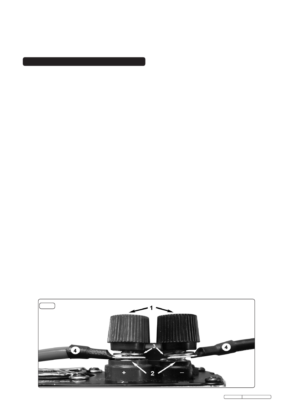
3.2.1 To attach the Battery Leads loosen the terminal caps (fig.1.1) on the rear of the inverter so that there is sufficient space
between the terminal bases (fig.1.2) and the washers (fig.1.3) to insert the battery lead fork connectors (fig.1.4).
3.2.2 Attach the Black battery lead fork connector to the Black/Negative terminal post on the inverter, and tighten the terminal
cap.
3.2.3 Attach the Red battery lead fork connector to the Red/Positive terminal post on the inverter, and tighten the terminal cap.
3.2.4 Check that the battery leads are secure.
3.3 Connecting to Battery Terminals.
NOTE! Check the battery is 12VDC. DO NOT use with a 6V or 24V battery
3.3.1 Ensure battery terminals are clean, if necessary clean away any corrosion.
3.3.2 Check to make sure the inverter is turned OFF and no flammable fumes are present.
3.3.3 Clip the red (+) battery clip to the red (+) terminal post on the battery.
3.3.4 Clip the black (-) battery clip to the black (-) terminal post on the battery.
3.3.5 Check all connections are secure.
3.4 Connection to Load.
NOTE! Most electrical appliances, tools etc, have a rating plate indicating the power consumption in Amps or Watts. Use
these ratings to ensure you remain within the inverters maximum capacity. If the rating is shown in Amps, multiply
the value by the voltage (230V) to determine the wattage.
3.4.1 Ensure that the inverter is switched OFF. Plug the equipment you wish to use into the inverter 3 pin socket or into the USB
port as required.
3.4.2 Make sure the load does not exceed the wattage rating of the inverter.
3.4.3 Switch the inverter on, check that everything is working and the green LED is lit.
WARNING! DO NOT connect the inverter to any AC distribution wiring or any AC load circuit in which the neutral conductor
is connected to ground (earth) or to the negative of the DC (battery) source.
NOTE! Some rechargeable devices do not operate well with a moderated sine wave inverter. They only operate from a
standard household outlet which provides a pure sine wave. It is recommended that these devices be operated
from a standard household outlet only. This problem does not occur with most battery operated equipment. Most
of these devices use a separate charger or transformer that is plugged into a separate AC socket.
3.5 Placement of Inverter.
3.5.1 For best and safest operation the inverter should be placed on a flat and stable surface.
3.5.2 Use only in a dry location, do not allow inverter to get wet.
3.5.3 Use in cool ambient temperature of between 0°C and 40°C. Do not place on or near a heating vent.
3.5.4 Allow sufficient space around the inverter for cooling. If the inverter overheats it will shut down and will not restart until it
has cooled down.
3.5.5
DO NOT use near flammable materials or anywhere that flammable gasses could accumulate.
3.5.6 The inverter may become uncomfortably hot during extended periods of full power use.
WARNING! DO NOT place on or near materials that may be affected by heat.
3. SETUP & OPERATION
Original Language Version
PI500.V3 Issue:1 - 31/03/11
2.2 Specifications.
Input Voltage: . . . . . . . . . . . . . . . . . . . . .12V DC
Output Voltage:. . . . . . . . . . . . . . . .230V AC
Continuous Output Wattage:. . . . . . . . . . 500W
Maximum Output Wattage: . . . . . . . 1000W
Output Frequency Range: . . . . . . . . . . . . . 50Hz
Dimensions (LxWxH): . . . . 230x105x60mm
Supply Connection: . . . . . . . . . . . . Battery Clips
fig.1