Fig 1, Introduction & specifications, Installation & assembly – Sealey TP97 User Manual
Page 2
2. intrOduCtiOn & speCifiCatiOns
this diesel and fuel oil transfer pump set is intended for use in a wide variety of situations in agricultural, industrial, marine and transport
environments. the pump is available in three versions to cover different voltages : tP97 for 12 volt systems, tP9724 for 24 volt systems and
tP97230 for use where mains power is available. the pump unit can be screwed onto storage containers and tanks and has an integral
priming lever which can also be used in emergencies to deliver small quantities of fuel in the event of power loss. the low maintenance pump
has a high quality, impact resistant housing and built in syphon protection.
specification .............. tp97 ................ tp9724 ................tp97230
Voltage.......................... 12V .................... 24V .........................230V
frequency...................... n/a ......................n/a ..........................50Hz
current type ...................dc ......................dc ......... single phaseAc
Power consumption .......14A .................... 10A........................... 1.8A
Performance ................180W ..................240W .......................320W
delivery.......................38 ltr/m .............. 43 ltr/m ................... 52 ltr/m
max delivery height ...... 9mtr ...................10mtr ....................... 15mtr
Weight ......................... 2.5kg .................. 2.5kg ........................2.5kg
General spec.
temperature of delivery medium ................................-10
°c to+35°c
length of suction hose ............................................................ 1.6mtr
length of delivery hose .............................................................. 4mtr
suction height ......................................................................... max. 2mtr
container connection .................................................... G2” and m64x4
length of connection cable ....................... 2mtr(230V) 3mtr(12/24V)
Protection type ...........................................................................IP24
noise level ............................................................................ 70dB(A)
3. installatiOn & assemBlY
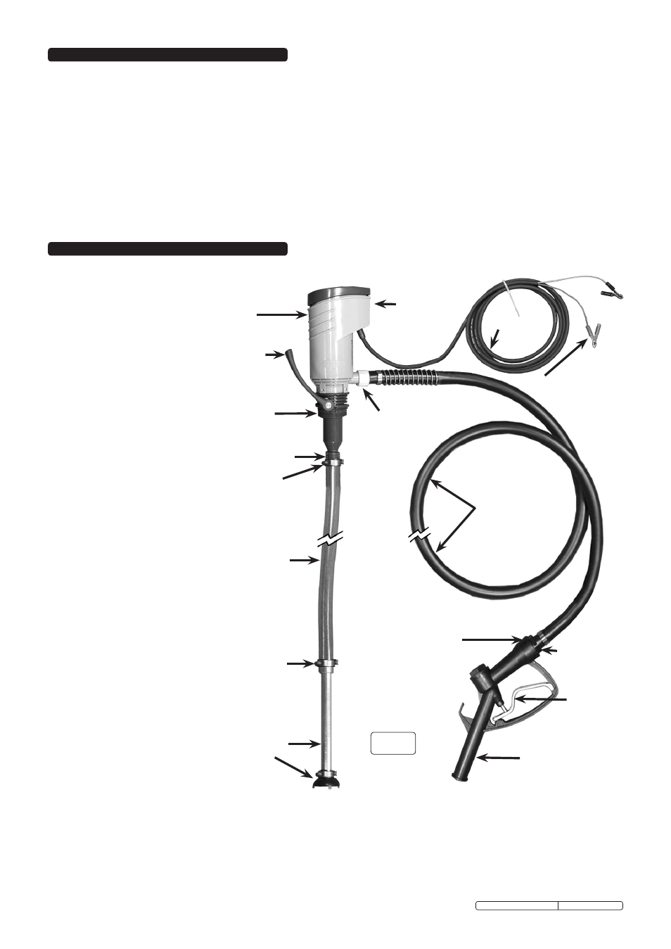
3.1 unpack the product and check that all parts are present with reference to the diagram below. If any items are damaged or missing
contact your sealey dealer immediately.
1. pump
housing
2. priming
hand lever.
3. dual thread
barrel
connector
4. suction union
5. Hose clamp
6. suction hose
9. standard
nozzle
12. female
connection
(trigger)
7. Hose clamp
16.power
cable
14. delivery
union
15.On/Off
switch
10.trigger
13.delivery
hose
11. male hose
connector
17. power cable
termination
8. suction pipe
with filter
3.2 assemBlY. (refer to fig.1)
3.2.1 Push the suction hose (6) onto
the suction pipe (8) by at least
20mm. secure the joint with
hose clamp (7).
3.2.2 cut the suction hose to length
bearing in mind that the pump
may be mounted to more than
one container and that the
filter must be always be under
the surface of the fuel even
when the fuel level is low.
3.2.3 slide the second hose clamp
(5) over the end of the suction
hose. Push the suction hose
over the suction union on the
pump (4). slide the hose
clamp up onto the joint and
tighten it.
3.2.4 Assemble the pump to the fuel
container. firstly feed the
suction hose into the container
until the pump is seated in the
aperture then rotate the pump
so that it screws firmly down
onto the container. the dual
thread arrangement on the
connector will automatically
pick up on either a coarse or
fine thread.
3.2.5 once mounted the head of the
pump can be rotated into any
position to bring the delivery
union into the ideal orientation
for connection of the delivery
hose.
3.2.6 A rubber washer is attached to
the end of the hose that is
contained within a spring.
remove the washer and place
it inside the nylon union nut.
screw the union nut onto the
delivery outlet (14) of the
pump and tighten.
3.2.7 screw the standard nozzle
assembly (9) onto the male
hose connector (11) on the
free end of the delivery hose.
fig 1
3.2.8 connect the pump to a suitable power source depending on which model you have. ensure that the voltage of your pump matches the
voltage of your power source. 230V models will have a mains plug attached. the power cables for 12 & 24V models are terminated with
battery clips (see fig.1 - 17).
3.3 INSTALLATION SITE. It is the responsibility of the owner of the equipment to ensure that the siting of the fuel container and
the installation and operation of the pump is carried out in such a way as to prevent any leakages that that could contaminate
drinking water for people or animals or water courses. The owner should liaise with local authorities, health and safety and
water authorities to ensure that the installation is safe.
Original Language Version
tP97, tP9724, tP97230 Issue: 3 - 22/03/10