Performance data 5. maintenance, Operation – Sealey TP96 User Manual
Page 2
6. PERFORMANCE DATA
5. MAINTENANCE
5.1 check the pump casing, suction and delivery tubes regularly for leaks.
5.2 Keep the pump clean for easy detection of leaks.
5.3 remove and clean the filter every 10 hours of operation or sooner if the transfer flow begins to decrease.
5.4 Dispose of environmentally hazardous parts in the proper manner.
tP96.V2, tP9624.V2 Issue no: 1 - 30/04/12
4. OPERATION
WARNING! Check to ensure you are connecting your pump to the correct voltage power supply for model.
4.1 Before each use, clean the inlet and outlet ports. remove any dust or packing material that may have collected during transport or
between uses.
4.2 Lower the suction tube (with filter attached) into the fuel storage tank.
4.3 Place the delivery nozzle in the fuel tank of the vehicle.
4.4 Attach the red battery clamp to the positive (+) terminal of the vehicle’s battery, and the black clamp to the negative (-) terminal.
4.5 Before turning the pump on, ensure that the delivery nozzle is in the ‘off’ position.
4.6 turn the switch ‘on’. the pump is capable of operating with the delivery nozzle closed for 2-3 minutes maximum.
4.7 Grip the nozzle firmly and squeeze the trigger to begin transferring fuel.
4.8 release the trigger to stop the fuel flow when the transfer is complete.
4.9 turn the pump switch ‘off’.
Note: the fuel pump may switch off automatically if there is insufficient voltage or a fault in the electrical connection. If this happens,
release the trigger handle, keeping the nozzle in place, and turn the pump switch off. Investigate the cause of the interruption.
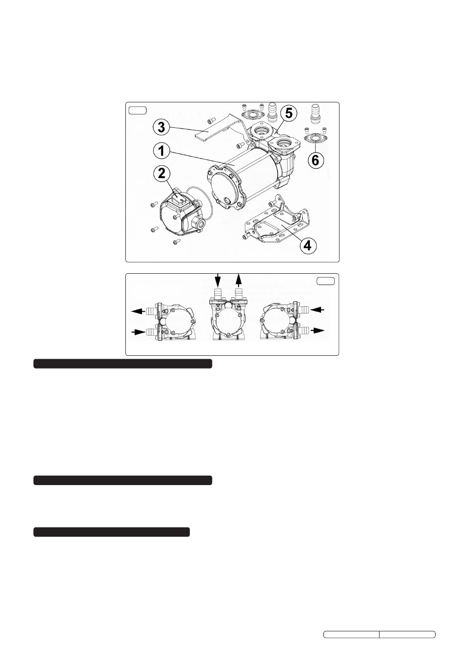
fig.3
fig.2
Original Language Version
3.4 Attach the handle (fig.2-3) to the upper part of the inlet/outlet casting (fig.2-5) using a single socket cap screw.
3.5 Attach the pipe fittings (fig.2-6) to the inlet/outlet casting (fig.2-5) using the screws provided.
3.6 the hose is supplied in a single length and should be cut in two to make the suction and delivery hoses. review your installation site to
decide on the lengths required and cut the hose accordingly.
3.7 Push the filter attachment into one end of the suction hose and secure it with one of the hose clips supplied. Identify the inlet port by
means of the flow arrow on the top of the inlet/outlet casting and then attach the hose to the inlet port. secure with a hose clip.
3.8 Insert the delivery nozzle provided into one end of the delivery hose and secure it with a hose clip. Attach the delivery hose to the outlet
port on the pump body and secure with a hose clip.
6.1 the graph in fig.4 refers to the following operating conditions:
Fluid: Diesel
Temperature: 20°c
Suction Conditions: the suction pipe and the pump are in such a position relative to the fluid level that a pressure of 0.3bar is
generated at the nominal flow rate. flow rate is shown as a function of back pressure.
6.2 under different suction conditions higher pressure values can be created that reduce the flow rate compared to the same back pressure
values.
6.3 to obtain the best performance, it is important to reduce the loss of suction pressure as much as possible by keeping the suction
filter clean and ensuring that the suction hose is of the correct diameter and as short as possible.