Fig.3 fig.4 fig.5, Assembly / pre-operation, Safety features – Sealey PWDM3600 User Manual
Page 3
3. ASSEMbLY / PRE-OPERATION
Unpack contents and check to ensure all parts are in good
condition. If you experience any problems contact your
dealer immediately.
3.1. ASSEMbLY. (See fig.1)
3.1.1. Attach the frame handle to the main frame by pushing the ends of
the handle into the vertical sockets welded to the back top cross
member seen in fig.1. Ensure that the holes in the ends of the frame
handle align with the holes in the vertical sockets. Secure the two
parts of the frame together by pushing a handle fixing (with black
knob) through both tubes. Lock each fixing using screw and nut.
3.1.2. Attach the hose hook to the side of the frame handle which has two
mounting holes, using using two cross head screws, nuts and
washers.
3.1.3. Attach the gun hook to the side of the frame handle which has one
mounting hole, using two screws, nuts and washers .
3.1.4. Attach the wheels by sliding the stub axle on each wheel into the
axle tubes that are welded on the underside of the frame. This will
involve turning the unit onto its sides. This should be done before oil
is added to the engine and before fuel is added to the tank. As each
wheel stub axle is inserted into the axle tubes, lock it in place by
inserting a locking bolt into the nuts welded on the tubes. Tighten
each bolt firmly.
3.1.5. Screw together the two halves of the lance as shown in fig.2.
3.1.6. Select an appropriate nozzle from the nozzle stowage area. Pull
back the spring loaded sleeve at the end of the lance and insert the
nozzle. Let go of the sleeve and check that the nozzle is firmly
gripped in the fitting. The nozzle selection is colour coded and offers
the following options.
BLACK
Low pressure wide angle spray for use with detergent.
RED
High pressure, 0° degree spray,
Very Aggressive.
YELLOW High pressure, 15° Spray angle, normal cleaning.
WHITE
High pressure, 40° Spray angle, normal cleaning.
GREEN High pressure, 25° Spray angle, normal cleaning.
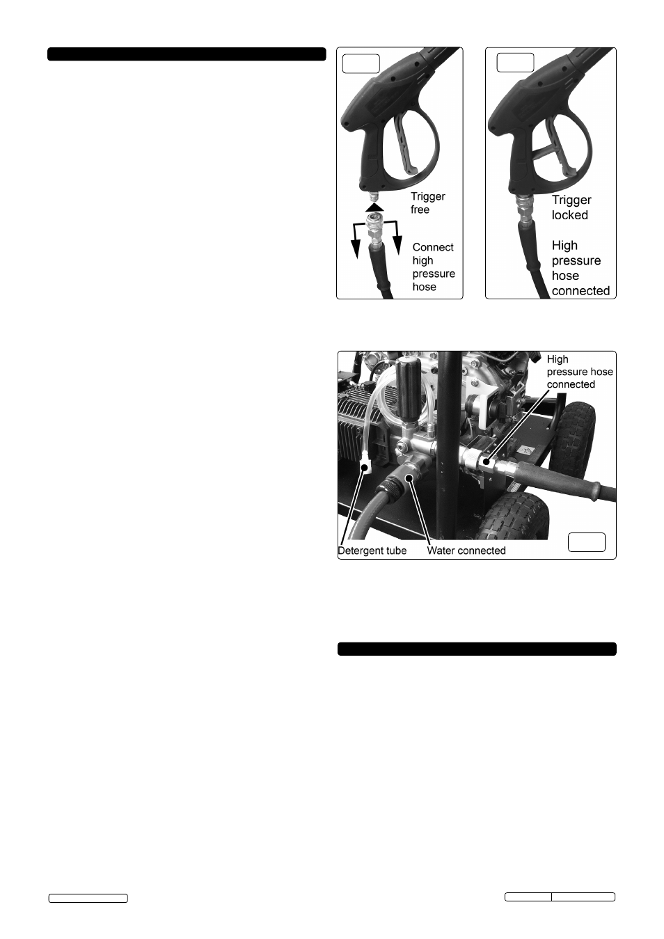
3.1.7. To attach the high pressure hose to the water inlet on the gun,
first pull back the spring loaded collar on the hose fitting and
push it onto the inlet on the gun and release the collar as
shown in fig.3 & fig.4.
3.1.8. Attach the other end of the high pressure hose to the pump
outlet as shown in fig.5. Pull back the brass sleeve on the
connection. Insert the hose and release the sleeve.
3.1.9. Connect the mains water supply hose to the pump inlet as
shown in fig.5. USE COLD WATER ONLY.
Note: The water supply hose must be reinforced and have an
internal diameter of 13mm (1/2”). The minimum water supply
rate must be at least equal to the washer flow rate.
3.2. DETERGENT DELIVERY.
3.2.1. Attach the BLACK low pressure nozzle to the end of the lance.
Remove the cap from a bottle of detergent and place the bottle
in front of the machine.
3.2.2. On the top of the pump outlet is a brass siphon injection fitting.
Push the detergent input pipe onto the fitting (fig.5) and place the
filter on the other end into the container of detergent ensuring
that it goes all the way to the bottom. When used with the low
pressure black nozzle, detergent will be drawn from the
container by siphonic action and will mix automatically with the
water from the pump. Use Sealey General Purpose Detergent,
AK130 (25ltr) or AK131 (5ltr). Sealey Traffic Film Remover is
also available,
AK132 (25ltr) or AK133 (5ltr).
3.3. ENGINE LUbRICATION.
3.3.1.
THE PRESSURE WASHER ENGINE IS SHIPPED FROM THE
FACTORY WITHOUT OIL. DO NOT ATTEMPT TO START
THE ENGINE BEFORE THE SUMP HAS BEEN FILLED WITH
THE CORRECT AMOUNT OF OIL. Refer to the section 7.2.
3.4. FUEL.
3.4.1. Fill the tank with fresh diesel fuel. Keep fuel level below the
fuel filter which sits in the neck of the tank.
3.5. PUMP.
3.5.1. The pump is supplied without engine oil. Fill with an approved
engine oil to the oil level before using the unit. The combined
oil filler cap and dipstick is on top of the pump. The oil level
can also be seen in the sight glass on the end of the pump.
3.6. SITING OF UNIT.
3.6.1. Ideally the unit should be used on level ground. Where this is
not possible the unit should not be inclined more than 20° in
any one direction.
fig.3
fig.4
fig.5
4. SAFETY FEATURES
4.1. THERMAL RELIEF VALVE.
4.1.1. A thermal relief valve is fitted to protect the machine from
overheating if the gun remains closed for an extended
period of time or if the nozzle becomes blocked. To prolong the
life of the washer every effort should be made to avoid
overheating. It is recommended that if the unit is not going to
be used for two minutes or more it should be switched off.
4.2. TRIGGER LOCK.
4.2.1. To prevent accidental starting of the pressure washer the
trigger can be locked as shown in fig.4 by pulling up the
lever built into the back of the trigger and pressing it until it
snaps into an indent in the handle. To release the locking lever
flex the trigger handle forwards and flip the lever out of the
indent and fold it back into the trigger. The trigger should be
locked whenever the washer is not in use.
4.3. LOW OIL SHUTDOWN.
4.3.1. The engine on this washer is equipped with a low oil shutdown
feature which stops the engine if the oil drops below a
specified level. Should the engine cut out, first check that it is
standing on a level surface. If the oil level is still low top it up
as described in Section 7.2.
3.7. RUNNING IN THE ENGINE.
3.7.1 For the first 20 hours of operation the unit should not be placed
under heavy load. After the first 20 hours change the oil.
Original Language Version
© Jack Sealey Limited
PWDM3600 Issue: 1 - 08/05/13