Fig.3 fig.4, Alignment procedure – Sealey MS070 User Manual
Page 2
of the rear wheel and insert the rod through the lower part of
the wheel. slide the right hand laser unit onto the rod and up
to the tyre, followed by the spring and clamp unit. Lightly
clamp the two units to the tyre in the position indicated in fig.2.
3.5
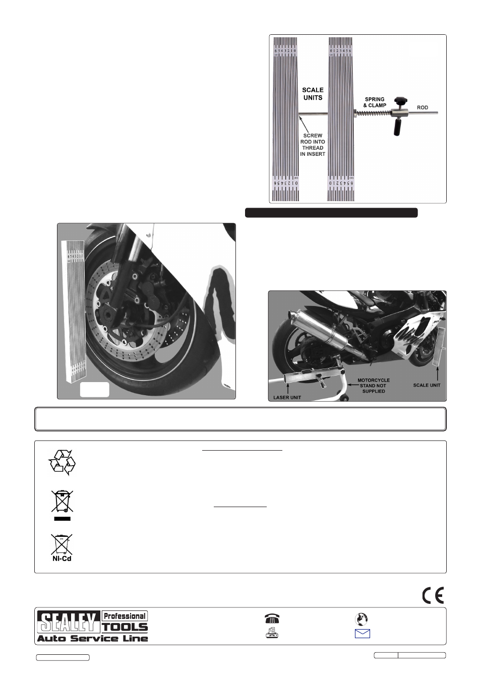
Attaching the scale units to the front wheel: referring to
fig.3, loosen the clamp and remove the clamp unit and spring
from the rod together with the right hand scale unit. Position
the left hand scale unit with the rod attached on the nearside
of the front wheel in a near vertical orientation and insert the
rod through the front part of the wheel. slide the right hand
scale unit onto the rod and up to the tyre, followed by the
spring and clamp unit. Ensure that the two scale units are
parallel to each other and then firmly clamp them to the tyre
in the position indicated in fig.4.
3.5.1
switch on the lasers and note the position of each beam on
the scales. If necessary, adjust the position/angle of the laser
units on the rear wheel to get the beams to appear on the
scales.
3.6
Front wheel position: the front wheel must be in the
straight ahead position before accurate alignment can take
place. If the beams are parallel with the scale lines the front
wheel is set dead ahead. If the beams are at an angle to the
scale lines, turn the wheel one way or the other until they are
parallel.
4. ALIGNMENT PROCEDURE
fig.3
fig.4
4.1
Alignment procedure: compare the readings on the scales.
If they are the same then the rear wheel is in alignment with
the front wheel. If they are not the same then it will be
necessary to operate the rear wheel adjusters. If the reading
is higher on the right hand scale, tighten the left hand
adjuster. If the reading is higher on the left hand scale, tighten
the right hand adjuster. When the wheels are in alignment,
finally tighten the rear wheel axle fixings.
NOTE: It is our policy to continually improve products and as such we reserve the right to alter data, specifications and component parts without prior notice.
IMPORTANT: no liability is accepted for incorrect use of this product.
WARRANTY: Guarantee is 12 months from purchase date, proof of which will be required for any claim.
INFORMATION: for a copy of our latest catalogue and promotions call us on 01284 757525 and leave your full name and address, including postcode.
01284 757500
01284 703534
Sole UK Distributor, Sealey Group,
Kempson Way, suffolk Business
Park
, Bury st. Edmunds, suffolk,
IP32 7Ar
www.sealey.co.uk
Web
Environmental Protection.
recycle unwanted materials instead of disposing of them as waste. All tools, accessories and packaging should
be sorted, taken to a recycle centre and disposed of in a manner which is compatible with the environment.
When the product is no longer required, it must be disposed of in an environmentally protective way. contact
your local solid waste authority for recycling information.
Battery Removal.
1. slide back and remove the lid from each battery box mounted on each laser unit.
2. remove the 2 AA batteries from each box and dispose of the batteries according to local authority guidelines.
under the Waste Batteries and Accumulators regulations 2009, Jack sealey Ltd are
required to inform potential purchasers of products containing batteries (as defined within these regulations), that they
are registered with Valpak’s registered compliance scheme.
Jack sealey Ltd’s Batteries Producer registration number (BPrn) is BPrn00705
Parts support is available for this product. To obtain a parts listing and/or diagram, please log on to www.sealey.co.uk, email
[email protected] or phone 01284 757500.
Original Language Version
Ms070 Issue: 2 - 20/07/12
© Jack sealey Limited