Fig.1 fig.2, Fig.3, Maintenance – Sealey WPB50A User Manual
Page 2
2. INTRODUCTION & SPECIFICATIONS
3. ASSEMBLY
4. OPERATION
Manufactured from corrosion resistant materials with a stainless steel motor case and noryl base cover.
Ideal for pumping water straight from a water butt directly onto your garden. Supplied with a two piece
aluminium swan neck extension pipe, adjustable flow control feature and snap on connector.
SPECIFICATION:
Model No: . . . . . . . . . . . . . . . . . . . . . . . . . . . . . . . . . . . . . . . . . . . . . . . . . . . . . . . . . . . . WPB50A
Cut-out: . . . . . . . . . . . . . . . . . . . . . . . . . . . . . . . . . . . . . . . . . . . . . . . . . . . . . . . . . . . . . .Automatic
Outlet O/D:. . . . . . . . . . . . . . . . . . . . . . . . . . . . . . . . . . . . . . . . . . . . . . . . . . . . . . . . . . . . . . .19mm
Maximum Output:. . . . . . . . . . . . . . . . . . . . . . . . . . . . . . . . . . . . . . . . . . . . . . . . . . 50ltr(13gal)/min
Maximum Head:. . . . . . . . . . . . . . . . . . . . . . . . . . . . . . . . . . . . . . . . . . . . . . . . . . . . . . . . . . . 10mtr
Minimum Water Depth: . . . . . . . . . . . . . . . . . . . . . . . . . . . . . . . . . . . . . . . . . . . . . . . . . . . . .50mm
Maximum Particle Size: . . . . . . . . . . . . . . . . . . . . . . . . . . . . . . . . . . . . . . . . . . . . . . . . . . . . 0.5mm
Motor Power: . . . . . . . . . . . . . . . . . . . . . . . . . . . . . . . . . . . . . . . . . . . . . . . . . . . . . . . . . . . . . 350W
Supply:. . . . . . . . . . . . . . . . . . . . . . . . . . . . . . . . . . . . . . . . . . . . . . . . . . . . . . . . . . . . . . . . . . .230V
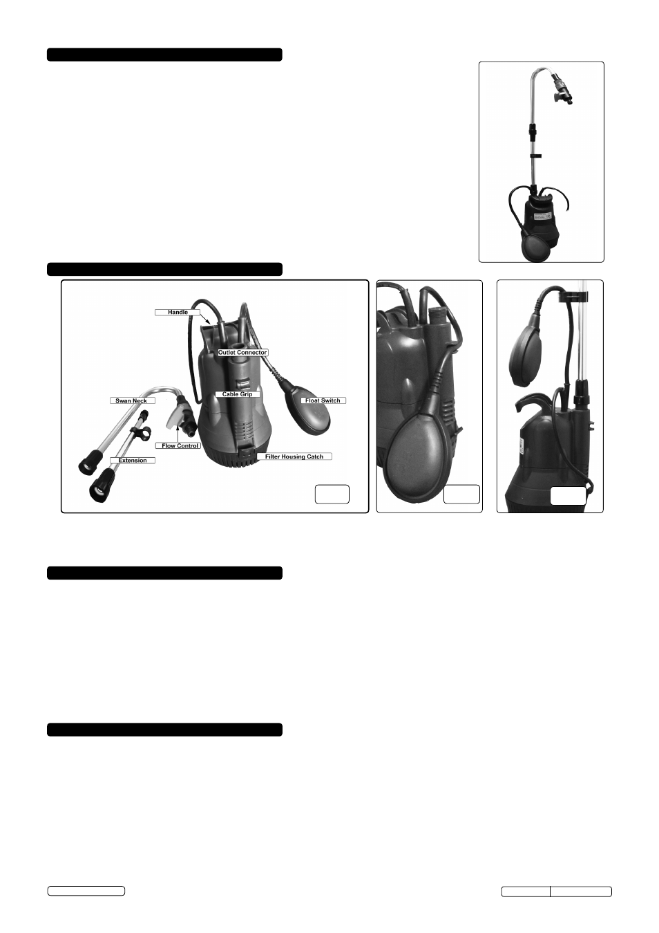
fig.1
fig.2
3.1.
DO NOT connect to the mains supply until the pump is immersed in the water butt.
3.2.
Screw the extension into the swan neck, then screw the assembly onto the outlet connector. (fig.1)
3.3.
Clip the float switch flex into the grip on the back of the pump unit (fig.2) allowing the float switch to rise and fall freely.
3.4.
The pump cut-off point may be altered by clipping the float switch flex to the grip fitted on the extension (fig.3), allowing the float switch
to operate at a higher water level relative to the pump.
4.1.
Place the pump unit in the water butt.
4.2.
The pump must be installed and used in an upright position.
4.3.
If silt is present on the bottom of the butt, place the pump on a brick so as to lift the base of the pump clear.
This will protect the pump
from
ingesting
debris.
4.4.
Connect hose pipe to the swan neck using a suitable female snap connector.
4.5.
Connect the pump to the
mains power supply; provided sufficient water is present to activate the float switch, the pump will now run.
4.6.
The output volume can be controlled by means of the flow control fitted to the snap connector. Maximum flow is achieved with the
handle of the valve in line with the pipe. Flow is stopped with the handle at 90° to the pipe.
4.7.
The float switch is provided to protect the motor from dry running and consequent overheating; it is not intended as an on/off switch.
4.8.
If the water flow is controlled by a cut-off device fitted to the hose end, be aware that stopping the water flow will not stop the pump. No
damage will accrue if the flow is stopped for short periods, but avoid prolonged running in this condition.
4.9.
The pump is not continuously rated:
DO NOT run for more than 30minutes continuously, and allow 10minutes cooling at the end of this
time.
5. MAINTENANCE
WARNING! With the exceptions listed below, all pump, float and electrical cable service maintenance and repair must only be
undertaken by an authorised service agent. Failure to observe this rule may be dangerous and will invalidate the warranty.
WARNING! Ensure the pump is disconnected from the mains power supply before attempting any service or maintenance.
5.1.
Keep all parts of the pump clean. Rinse, drain and allow to dry before storing the pump.
5.2.
Regularly check the inlet filter in the base of the pump to ensure that there are no blockages. To access the filter, undo the filter
housing catch (fig.1) and remove the filter housing. Remove the circular foam filter element and wash in warm water. Replace the filter
and refit the housing onto the pump inlet.
DO NOT dismantle any other part of the unit.
Original Language Version
WPB50A Issue: 1 - 20/11/13
© Jack Sealey Limited
fig.3