Fig. 2 fig. 3, Fig.3, Fig.2 – Medal Sports BL17201 User Manual
Page 7: Electronic connections diagram
Advertising
6
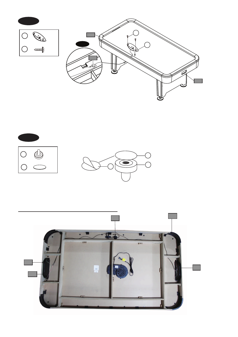
FIG. 2
FIG. 3
FIG.3
9. Tear off the backside paper of the Felt Pad (#8) and stick them at the bottom of the Pushers (#6).
See FIG.3.
FIG.2
7. Attach the Scorer (#9) to the top rail of the Main Cabinet (#1) using two Screws (#A5).
See FIG.2 .
8. Thread the Scorer Wire through the hole of the side apron to Insert the Scorer Wire into the Connect
Box (#P4).
See FIG.2 & 2A.
P4
P6
P7
P7
P2
X 2
X 1
9
A5
X 2
6
X 2
8
P3
P5
A5
9
P4
FIG. 2A
8
6
8
Electronic Connections Diagram
Advertising
This manual is related to the following products: